The Class of 2009 - 2010
Project - 1962 Tiger Cub
Project - 1962 Tiger Cub
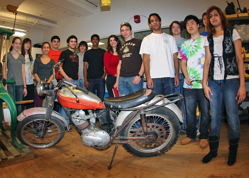
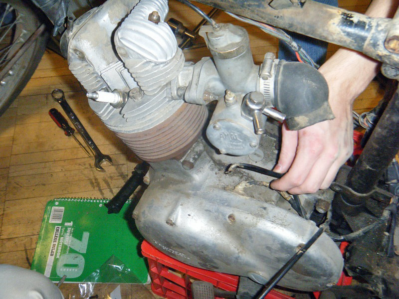
When we first started to disassemble the bike, the engine was one of the things that we focused on. It's importance to the success of the project is clear. The bike had been parked for several years prior to the time that it was purchased for the class and the picture gives a good idea of what kind of condition the exterior of the engine was in.
The cylinder was rusty and some pieces were missing or had been replaced with non-standard parts. However, it was a good starting point for restoring this bike.
The Triumph Tiger Cub has a 4-cycle engine with one cylinder. This means that one out of every four piston movements is the combustion of the gas and air mixture. The cycles are as follows:
Intake - the piston moves downward while the intake valve opens, creating suction which draws the fuel/air mixture into the cylinder.
Compression - the intake valve closes and the piston begins moving upwards again, compressing the gas/air mixture. This compression also heats the mixture. The amount of combustion is determined by the shape of the piston, which can be changed to alter compression ratios. A higher compression ratio puts more stress on the engine, and requires a higher octane gasoline, while also increasing engine performance.
In our bike, we opted to use a piston with mid-level compression ratio, rather than Glenn’s 10.5 to one piston which would have required either leaded gasoline or extremely high octane fuel (higher than premium gasoline) to run properly in our system.
Power - the spark plug fires approximately when the piston is approximately at its highest point (top dead center) initiating combustion. The gas rapidly burns and increases pressure in the cylinder, pushing the piston back downwards.
Exhaust - the exhaust valve opens, and the gases remaining from combustion are pushed out by the pressure from the cylinder moving upward
The interaction of the piston and the valves determines max RPM, since at extremely high RPM the piston moves up and down so quickly in the cylinder, that the valves cannot open and shut quickly enough.
|
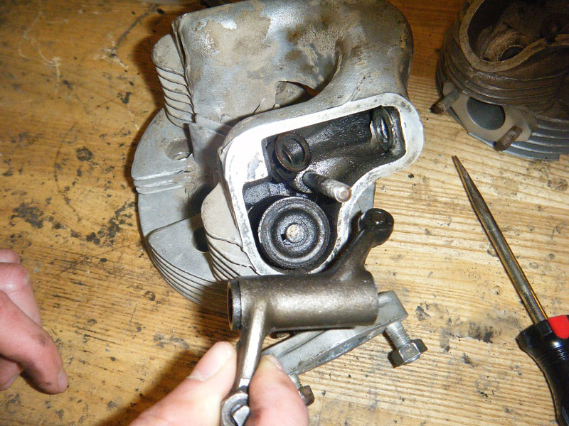
After the engine unit was removed from the frame, the cylinder head was unbolted and lifted off.
The cylinder and piston were also removed from the lower end of the engine. Disassembly of the cylinder head began with the removal of the rocker covers. Next, the rocker arms were removed as can be seen in the picture. The picture also gives a better idea of the condition of the cylinder head. |
|
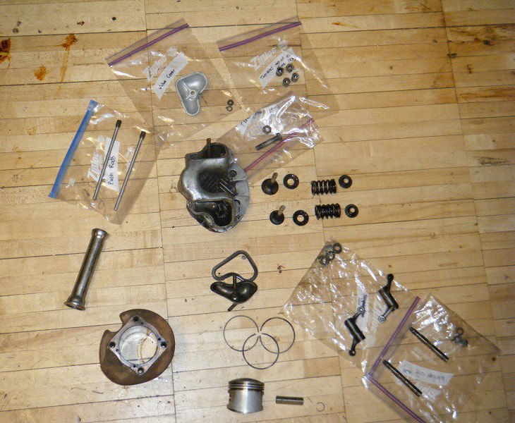
The valves were removed by compressing the valve springs with a C-clamp and a special tool while the clips holding the spring in place could be removed. This was a tricky operation, as the clips are small, but putting them back was much more difficult. With the valves removed, the top end of the engine was totally disassembled and restoration work could begin. |
|
With the engine apart cleaning, the first step of restoration, could begin. Trying to clean the head in the parts cleaner was ineffective. Blasting it with an abrasive glass bead media proved to be much more effective and cleaned it up pretty nicely. Most of the other parts that were reused were simply wiped down prior to the start of reassembly. The piston had to discarded because the diameter of the cylinder bore was too great for the piston. Repair work on the top end of the engine includes resurfacing of the valves, cutting of new valve seats, and boring the cylinder. |
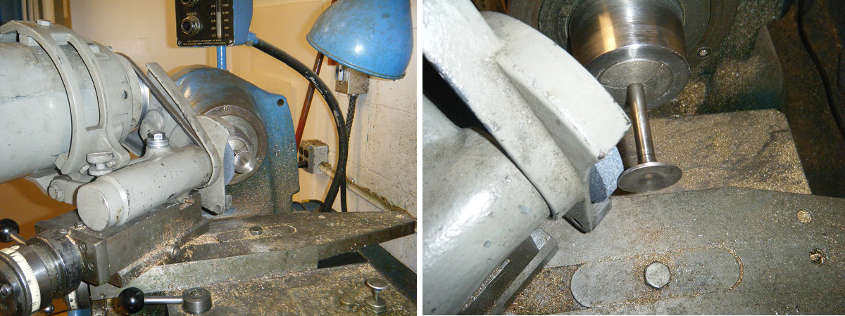
The valve surfaces needed to be refinished in order to properly seal the cylinder and yield optimum performance.
The valves were reworked using a grinder and a lathe as in the picture.
The valves were reworked using a grinder and a lathe as in the picture.
New valve seats were also cut into the cylinder head. Instead of a single 45 degree angle as would have been usual, the new valve seats were cut to 31, 46, and 61 degrees. This three-angle valve job results in a smaller contact area between the valve and the seat. This characteristic results in a better performing and more durable arrangement.
The valve seats were cut by hand using a kit designed especially for the purpose. After the proper dimensions were obtained, the seats were lapped by placing grinding compound on the valve and rotating it against the seat to even out the surfaces and provide an even tighter seal. The valves were then replaced.
The purpose of this work was to create a good seat for the valves, which now contact their seats in small, thin circles. In determining how much of the valve hits the seat, we struck a happy medium between two competing ideas.
A very small contact area would have high performance for a short amount of time, since it would seal very well but would have poor heat dissipation. On the other hand, a larger contact area would have better heat dissipation but would make a worse seal.
The next step in the overhaul will be to bore the cylinder to 0.060 in. over standard. This step is necessary because the engine was poorly bored previously. When it was bored previously, the person who did the work cut it to exactly .040 over and didn’t hone it to remove the boring marks. As the engine was run, the piston gradually wore down the small grooves from the previous boring, making the cylinder significantly larger and robbing the engine of power.
This is extremely unfortunate, because it means that we will be required to bore the engine to .060 over, which is the maximum amount that can be done, since the quality of metal in the engine deteriorates the further we bore from the center. The engine will need to be replaced if it requires any more boring.
A new 0.060 over piston with a 9:1 compression ratio has been ordered. With this step, the overhaul of the top end of the engine will be nearly complete.
|
Brakes
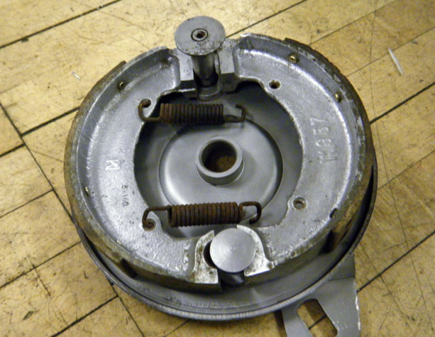
Our Triumph Tiger Cub uses drum brakes. Drum brakes are brakes in which two brake shoes push out against the drum, which is an inner surface of the wheel. This causes friction and stops the wheel from rotating. In the photo you can see the two brake shoes that are attached by two springs (unattached in this picture). These springs exert an inward force on both brake shoes. What causes the brake shoes to push out is the rotation of the small piece at the top. This piece is sort of shaped like an elliptic cylinder. |
When the brake shoes are separated by only the minor axis, shorter radius, of the elliptic cylinder, they are closer together. However, as the elliptic cylinder turns, a longer axis comes between the two brake shoes, pushing them further apart.
Restoration
Our restoration of the brakes thus far has been mostly cleaning and separating the parts that were rusted together.
We used a lot of Scoth-Brite Hand Pads, similar to steel wool, and degreaser to remove as much dirt, grease, and rust as possible.
Our restoration of the brakes thus far has been mostly cleaning and separating the parts that were rusted together.
We used a lot of Scoth-Brite Hand Pads, similar to steel wool, and degreaser to remove as much dirt, grease, and rust as possible.
|
For one brake, the elliptic cylinder was especially rusted and took a lot of de-rusting spray and a lot of force to free.
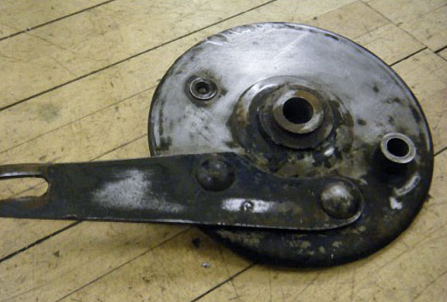
We also used the sand blaster to remove coats of paint and dirt. It worked really well. The picture is of the brake we are still working on cleaning. You can easily tell the difference between the half we have started to clean and the half we haven’t. This brake is harder to clean than the other and is requiring us to sand off the paint manually before putting it in the sand blaster. |
Asbestos
We always try to keep what we are cleaning damp so that we don’t produce any dust that could contain asbestos.
Asbestos is a good material for brakes because it is strong and can withstand high temperatures. However, asbestos fibers are long and thin. When breathed in, they can puncture the lungs and thus are extremely dangerous.
Before the 1980s, the dangers of asbestos were not known so asbestos was widely used in brakes. Our Triumph Tiger Cub was made in 1962, so it is likely that it was made with asbestos.
|
Frame disassembly
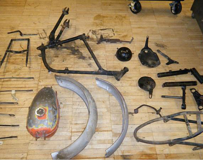
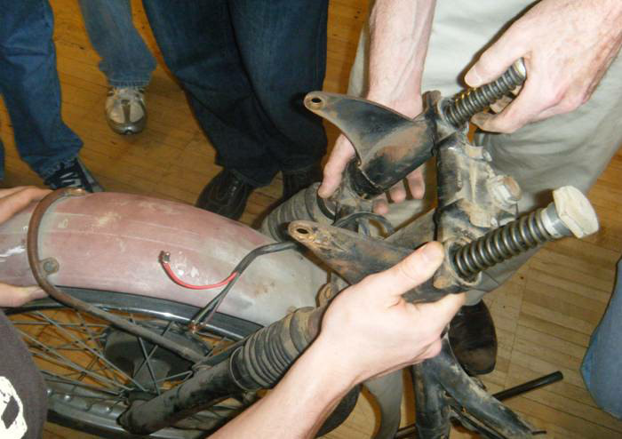
Overall the disassembly of the frame went smoothly. There were some problems with rusted, hard to reach and damaged bolts. However, with some innovative tool set-ups, we were able to get the job done. Other than rust, caked on grease, and a few dents, which can be expected from a bike manufactured in '62, the Cub frame was in good shape. A crack was found in the front fork shroud and the swing-arm bushings appeared to be worn. |
Over the past several weeks, our group has been working to prep the frame for powder-coating, repair the worn rear swing-arm, and design a part for the cracked front shroud. Prepping the frame for powder-coating involved first removing all the caked on grease before sending all the components through the parts cleaner.
We had to do some body work on the rear license plate holder to hammer out all the dents. In terms of the swing-arm, we were able to press out the bushings and are now waiting for the powder-coating to be finished before we replace them with the new bushings we ordered.
The cracked fork shroud was damaged beyond repair, so we drew up the part using Pro E CAD software and are currently in the process of machining a replacement.
Suspension
The '62 Triumph Tiger Cub suspension system is a collection of springs and damping mechanisms which serve two main purposes.
The '62 Triumph Tiger Cub suspension system is a collection of springs and damping mechanisms which serve two main purposes.
The suspension optimizes braking and handling by ensuring both wheels maintain contact with the ground, while providing safety and comfort by isolating the passenger from jolts and vibrations that occur while on the road.
It can be divided into two main components, the front fork and the rear swing-arm, which connect the front and rear wheels/axels, respectively, to the frame.
It can be divided into two main components, the front fork and the rear swing-arm, which connect the front and rear wheels/axels, respectively, to the frame.
|
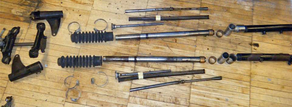
The '62 Tiger Cub uses a telescopic front fork with fork tubes which house the shock absorbers. "Telescopic" highlights the fact that the fork will compress and extend to highlight the inconsistencies in the road. The front fork was also in relatively good shape. Restoration has mainly involved draining and eventual replacement of the fork oil, a thorough cleaning in the parts cleaner/sand blaster, removal of rust by sanding, and repair of the fork shroud. |

