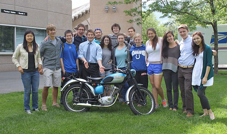
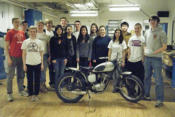
The Class of 2011 - 2012
Project - 1964 Tiger Cub
Project - 1964 Tiger Cub
|
“The disappearance of tools from our common education is the first step toward a wider ignorance of the world of artefacts that we inhabit.” |
|
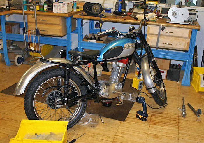
Frame - Day One
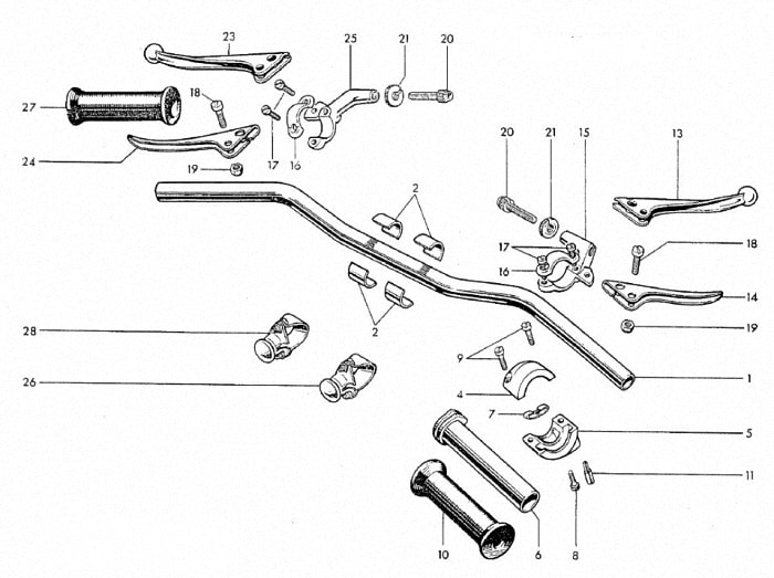
The engine has been removed and we are ready to start disassembling the frame. We started by removing the handlebars. It was important to remove these first so that we could allow room for the other groups to begin their own disassembly.
It may seem like removing the handlebars would be a relatively simple task, but they actually contained many complex components that had to be disassembled individually.
Note particularly the four pieces numbered item 2. These are called packing pieces and are fitted specifically to the handlebars, so we had to be sure not to lose them.
There is an engraved ribbing pattern on the handlebars that prevents them from slipping and moving backward or forward while the machine is in motion.
|
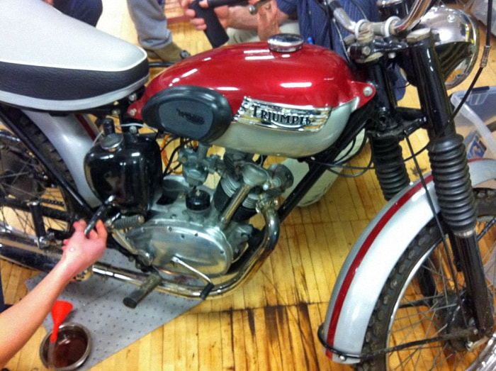
Our bike was missing the left handlebar grip (no. 27) but luckily we had the right handlebar grip, seeing that this piece is needed to rev up the engine.
Another important piece is no. 24, the clutch lever, which the rider pulls to take in the clutch to shift gears. No. 14 is the brake lever, which controls the front brake. We continued the disassembly of the frame, focusing on the big pieces, which will later have to be disassembled even further into the individual parts so that they can be sent to be powder-coated. |
|
|
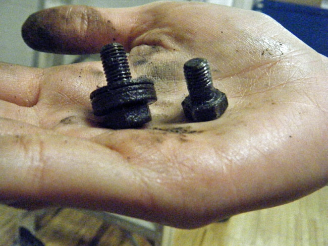
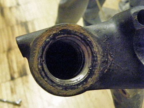
These bolts are from the bottom rod pieces of the front fork. Notice that one bolt has three washers stacked on it, while the other has just one.
Each bolt should be the same length and have only one washer. The previous owner, however, presumably did not have two bolts of the same length and instead placed multiple washers on the longer bolt to keep it from going in too far and piercing through the other side of the frame. This causes extra wear on the frame and, stylistically, it is a fashion no-no. Somebody call the fashion police! |
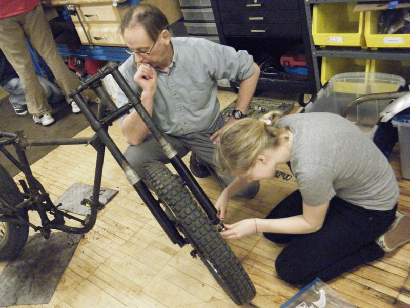
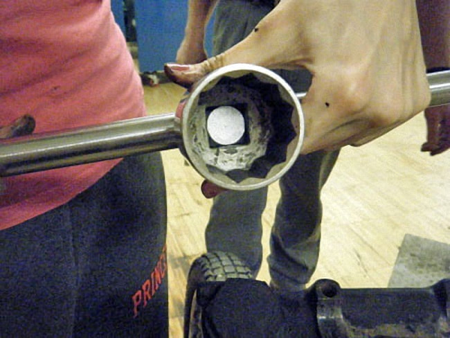
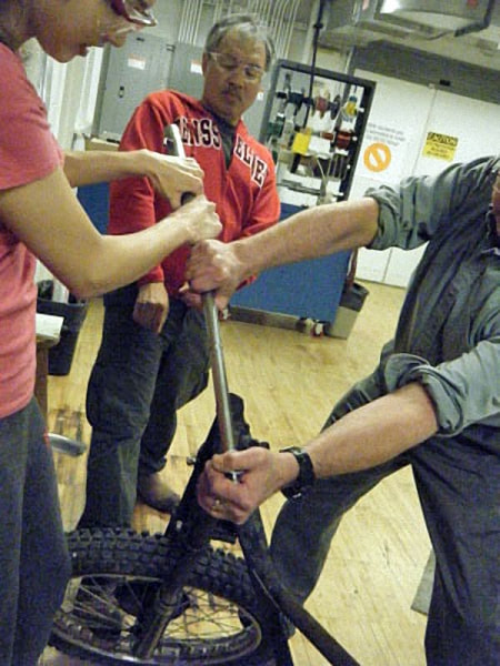
We used a giant socket wrench to loosen the giant bolt that held the top of the forks in place on the frame. It had an extra long, adjustable handle that gave extra leverage.
|
Because the bolt was so hard to undo, the extra-long handle gave us extra leverage and made the job of loosening the nut much easier.
|
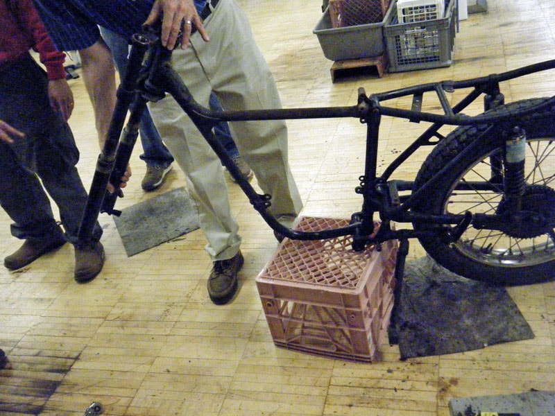
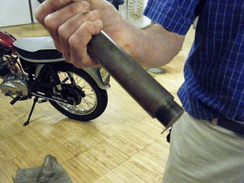
In order to continue taking apart the forks, we had to hammer the especially jammed stanchions out and used a special tool created by Glenn which screwed into the top so we could hammer that instead and not damage the stanchion nor the top yoke.
|
|
|
To help remove the stanchions, we also placed a wedge in the slit in bottom yoke in an attempt to ease open the hole holding them in place.
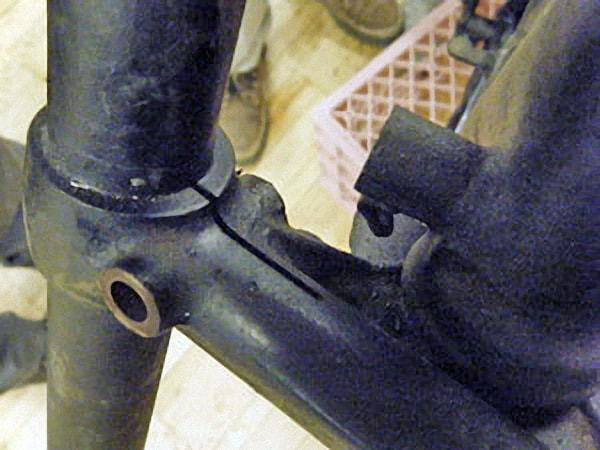
The seat mounts which are used to attach the seat to the frame were poorly cut by someone else and welded on with sub-par craftsmanship. We took some measurements from the current seat mount/frame configuration and Glenn used CAD to draw up a 3D model of the new ones we need to create.
|
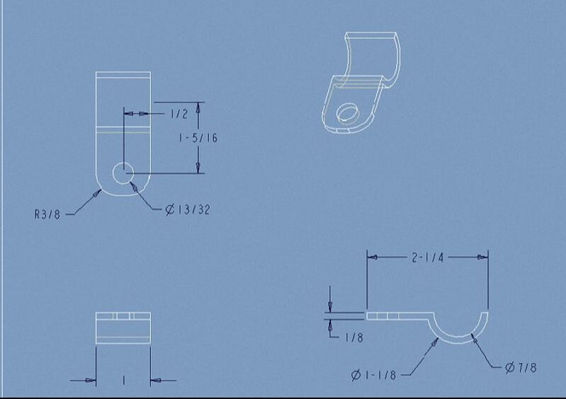
The diagram shows one seat mount (the two are identical) from three different angles and includes the measurements for each part. After creating the diagram, Glenn created code for a program that will use a machine to cut out the seat mounts from a given block of metal. The seat mounts were finished and looking really nice (they also fit perfectly to the frame), so we had to decide on placement for them to be welded on. |
We started today by filing the edges of the seat mounts to get rid of all the little shards still attached. Then we fit the seat mounts to the frame - 13.9 inches from the U-bend. After holding them in place with c-clamps, we watched as Glenn welded the mounts to the frame with the welding system that uses Tungsten metal and Argon gas in the process. The welds turned out really well.
We need to get the frame to the powder-coaters ASAP, so we started taking an inventory of everything that can be powder coated and finished getting all parts of the frame ready.
We don’t have to clean the frame pieces ourselves; the powder coaters will sand-blast the frame themselves to ensure the pieces have a finish the coating will adhere to well.
We had to pound out the bushes from the swing-arm with a specially designed tool so that they do not get painted into place during powder coating. We have a new set of bushes and can press them in when the swing-arm comes back.
We also designed a piece on CAD that will cover the holes in the yokes so the powder coating does not get into them. Glenn will make two of these pieces, most likely manually on the lathe.
We also had to remove a few last bolts from various parts of the frame as we don’t want any removable pieces left in when we send the frame for coating. It's now all set aside and ready to be sent out.
Fork Caps
We made new fork caps on the lathe. Starting with a solid aluminium cylinder, we used a drill bit in the lathe to first hollow out a cylinder with the correct diameter in one end of the aluminum piece. Then we used a bit with a special end and put the machine on automatic in order to put threads into the piece.
We repeated the same process on the other end and then cut the aluminium piece down the middle so that we had two identical caps. We put them on the forks and they fit!
|
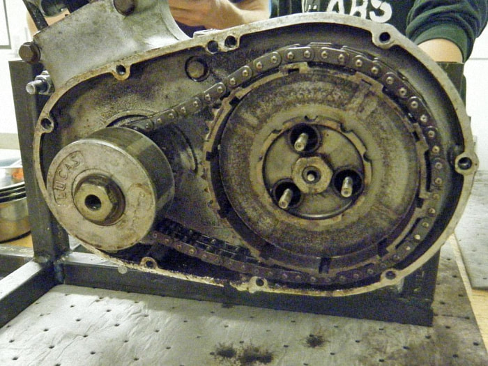
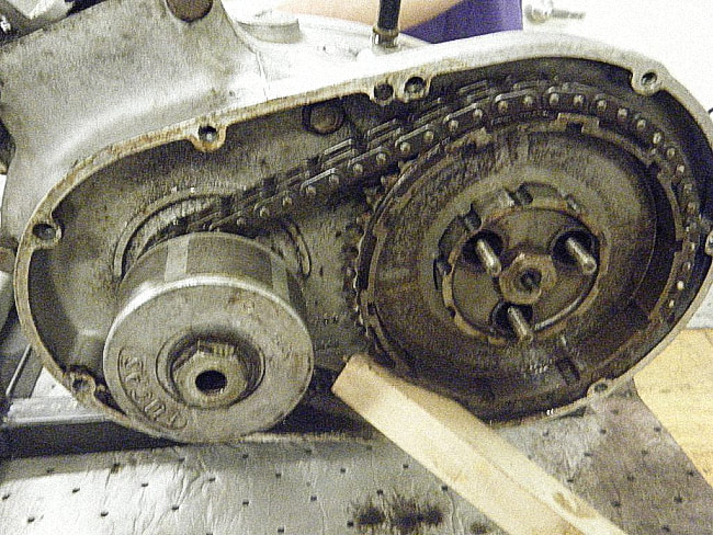
Clutch/Primary Chain
Team members: Alison and Sherry For the first day we studied the function of the clutch and found it transmits power from the engine to the transmission by means of a primary chain. It's made up of a series of spring-loaded plates which when separated (it's controlled by the clutch lever on the left handle bar and connected by a cable) means the transmission and power are not connected and the rear wheel of the motorcycle does not turn. We also found it uses two types of plates (friction and steel). |
|
Professor Littman showed us the adjustor, which has a round end that makes contact with a flat surface. When we take apart the clutch of the bike, we could adjust how much this piece protrudes.
|
|
|
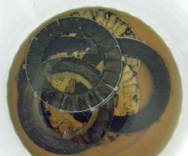
Finally we were able to do some work. First we removed the three cups, springs and nuts that protrude from the pressure plate.
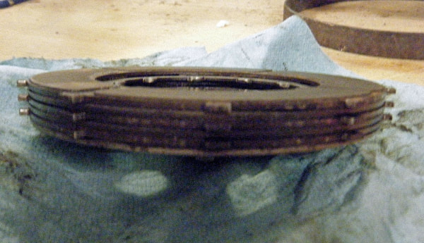
The six plates behind the pressure plate should have been separated, but the first five were stuck together. After some resistance, we decided to leave them be and work on disassembling the rest of the clutch.
The six plates behind the pressure plate should have been separated, but the first five were stuck together. After some resistance, we decided to leave them be and work on disassembling the rest of the clutch.
|
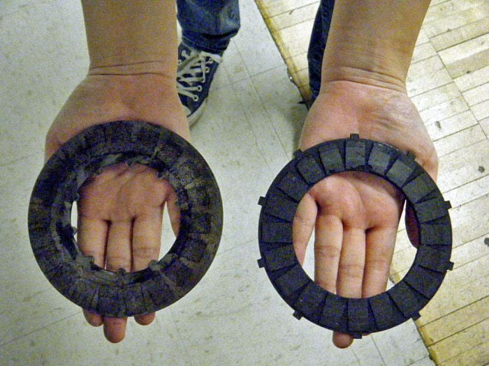
We compared the two types of plates. The first type had padding and lugs on the outer diameter which drive the transmission input shaft. The second type of plate did not have padding and had lugs on the inner diameter. Of the space between adjacent lugs, one space was not of equal size. These plates are driven by the engine crankshaft. |
|
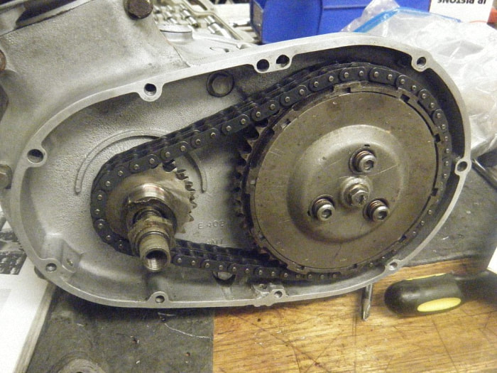
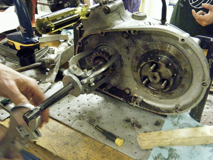
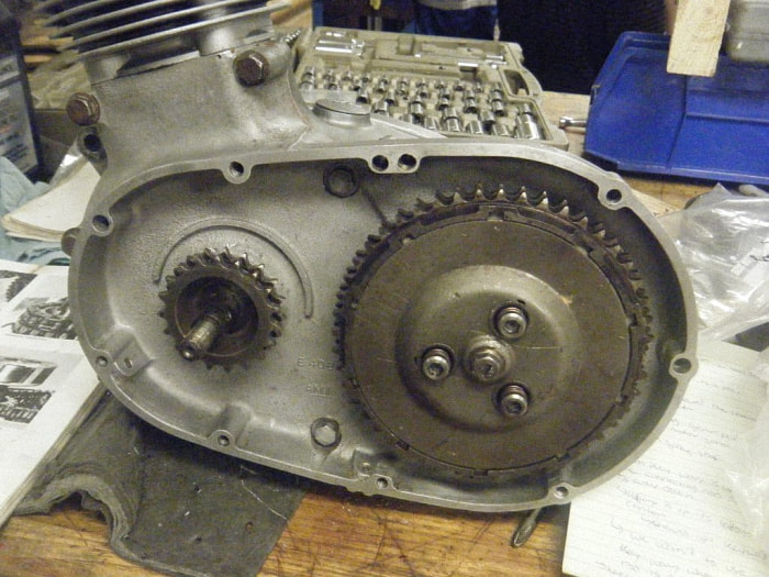
In order to remove the chain, we first had to take off the alternator rotor and the engine sprocket. Using Yield allowed us to unscrew the one sprocket and rotor nut as well as the tab washer. We used a piece of wood to stop everything rotating.
Afterwards, we used a gear puller to remove the magnetic alternator rotor. This revealed the engine sprocket to us, which we used the gear puller to remove as well.
Afterwards, we used a gear puller to remove the magnetic alternator rotor. This revealed the engine sprocket to us, which we used the gear puller to remove as well.
|
|
|
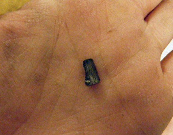
In the center of the engine sprocket was a distance piece. This distance piece had two keyways and a half-moon-shaped key in one of them.
These steps required a lot of force – so much that the chain kept slipping and we had to hold the crankcase assembly down. We had to recognize which keyway was the one we needed, and we noted it was chewed up from use. Just to make sure though, when the keyway we needed was rotated upwards, the connecting rod in the crankcase assembly was about 30 degrees after top dead center. |
The connecting rod moves up and down in an oval-shaped motion in correspondence to the spinning of the chain and sprockets. We also noted that when the keyway we needed was rotated down, the connecting rod was at bottom dead center and hidden in the crankcase assembly.
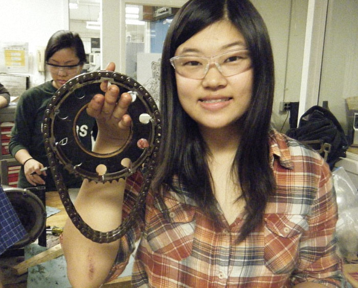
After the removal of the engine sprocket, we were able to remove the primary chain and the clutch sprocket.
After the removal of the engine sprocket, we were able to remove the primary chain and the clutch sprocket.
|
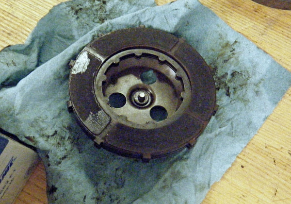
Glenn said we had to purchase a new primary chain, of which dimensions were: 62 links, duplex, 3/8 inches by 7/32 inches Our last steps in disassembly involved using a strap wrench to hold the clutch basket (to prevent it from slipping) and a ratchet wrench to unscrew a nut. We then used a puller that Glenn had made to remove the clutch basket. We will not be disassembling the clutch basket further, but it contains a center piece with three driving cups, rubber pieces, and a backing plate. |
|
Working on Tiger Cub ’62
|
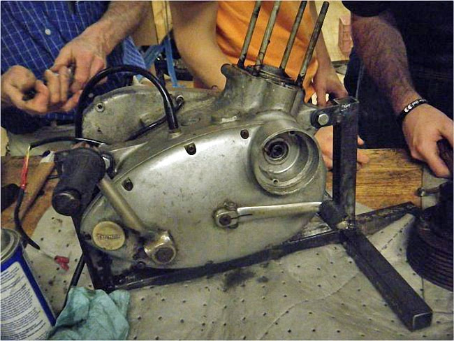
Today we took a break from working on the clutch by assisting John, who is representing his year, and trying to fix the Tiger Cub ’62.
There is a vibration in the engine and in order to make a diagnosis, John tried to remove the engine from the rest of the motorcycle. This is a more difficult task than it sounds, for two main reasons... ...first, we had to work around the frame and other built in parts of the motorcycle meaning there was limited room and movement, so it took a long time to remove the necessary parts... |
|
...and second, the tools in the shop were not organized or in the correct locations. At one point during the day when we needed an Allen key (wrench), there were none in the cabinet.
Finally, John found a container full of them, however they were loose, not in a set. So then we spent a little under ten minutes looking through the loose Allen keys, which were also not well labelled. It was upsetting that this took so long, because it is preventable.
Finally, John found a container full of them, however they were loose, not in a set. So then we spent a little under ten minutes looking through the loose Allen keys, which were also not well labelled. It was upsetting that this took so long, because it is preventable.
Back to our clutch and we decided the best way to proceed with the inspection was to measure the different parts. We used The Triumph Workshop Inspection Manual as a reference.
Additionally, we examined the sprockets and plates in a qualitative manner. We found that the ends of the teeth of the clutch and engine sprocket were a little rounded. Also, we examined the plain plates for flatness and stickiness. They were flat, but a little sticky.
Today was a relatively light day. We basically inspected all of the parts of the clutch and got an idea about which parts we need to replace. The parts we initially decided to replace are the plates and primary chain.
|
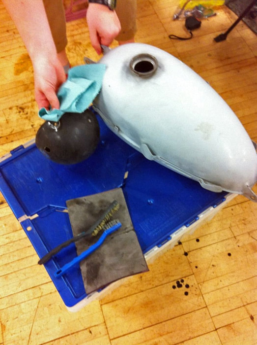
Additionally, Chris showed us and the frame group the ABC’s of painting. He stressed it is more of an art form – we need to start spraying off the piece and then across to apply an even coat of paint. Further, it is important to try to minimize running of the paint. Then in the lab, we were prepping the gas tank and the head light cover for painting. Specifically, we were trying to remove all of the rust. We used the wire brush and emery paper to do this. Although this task seems easy, it took a lot of time to make the covers smooth and remove rust from hard to reach areas. With disassembly of the clutch finished, we sought out other tasks. These included sanding the headlight piece, which was a half of a hollow sphere. Then we picked up a bigger task, which consumed a great amount of our time in the class. |
We each took a cover:
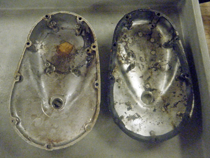
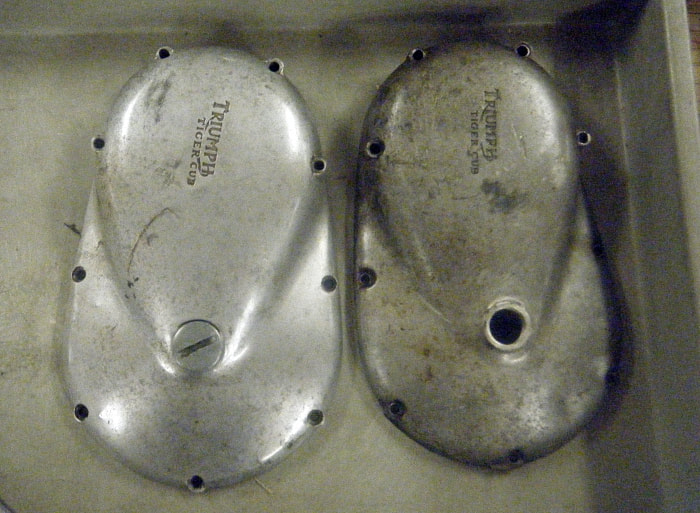
Alison took the transmission cover and Sherry took the clutch cover. These cases contained many deep scratches and cuts that needed to be sanded out.
The clutch cover from the original bike wasn’t in good enough condition to use again as there was a splotch of glue on the inside. Chris took us to the storage shed and we picked out another clutch case that matched ours.
The pictures of the covers before sanding are shown below:
|
|
Serious Sanding!
This week we realized how much work we had to complete on the clutch covers. Alison’s cover was not too damaged, but Sherry’s cover had huge gashes in it. In fact, it was so bad John did not think Sherry would be able to remove all of the deep marks. So, to better assist us in our attempt to sand the covers, we requested 40, 180, 360, 400 and 600 grade emery paper.
To get the smoothest results for the cover, first use the coarsest grade then moved onto a smoother paper. By the end of this week, we noticed considerable improvements in the cover; many of the marks were gone or faded.
However now the cover seemed rough and uneven, so for next week we have to start evening out the surface, and then use the finer grades (higher numbers) to give them a smooth finish.
Continuing our sanding journey, we venturing out into the wild (read: E-quad courtyard). Here, Alison showed Sherry the blister on her thumb – popped and painful from sanding so diligently.
By now we had invested our energies and efforts into this sanding project – it became a matter of pride and honor. Even so, we wondered if there was a machine that could perform this task.
|
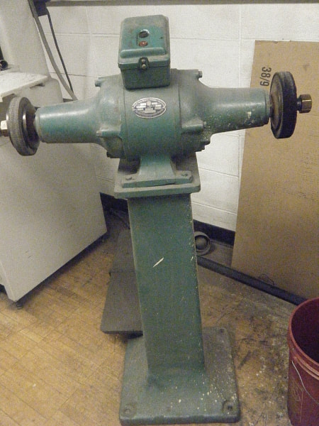
Alas, we learned that the surface of human fingers could do a better job than a machine! By Week 11 we are getting close to finishing the covers, however it is still does not have the shine of the previous year’s motorcycle. So to take any last roughness of the covers, we finished our sanding in the sink. Then, we had Prof. Littman use the Scotch Brightener machine to make it really smooth. Essentially, the machine is a spinning wheel covered in fine grade sand paper. The wheel spins really quickly (3600 rpm) which takes off any final layer of rough metal from the covers. After this, we used a billow sponge and polish to shine the cover. This made the covers really shine and appear smooth to the touch. Glenn told us these covers were much better than last year's! |
|
Assembly!
This week we were able to put the clutch back together. We put the clutch sprocket and housing, and the engine sprocket on, before we realized we needed to fit both of them at the same time along with the primary chain! Careful adherence to the workshop manual allowed us to determine which pieces were to be put on first, but we then realized half of our key was sheared off and stuck in the clutch sprocket. We resolved to finish up on Thursday, after Glenn had made a new key for us. On Thursday, we refitted the whole primary drive assembly using the new key. Glenn had bought new clutch plates so we soaked them in oil before fitting them in place. Afterwards, we put the clutch cover on. Overall, we made many errors but luckily, none were fatal. It was a great learning experience as well as a relief to be doing something other than sanding! Completion? Yes!!! On 4/30/12, we drove to the DMV in Lawrenceville to obtain our motorcycle permits. After arriving, realizing Alison did not have her 6 point ID, she drove back to Princeton with Sherry’s phone (GPS). She picked up her passport whilst Sherry took the motorcycle test, and luckily, Alison was able to pick up Sherry’s contact lenses when Sherry failed the vision test at the DMV. Alison got back to the DMV (after Sherry’s phone died and she had to ask someone for directions) and passed her test as well. |
|
The Wire Harness
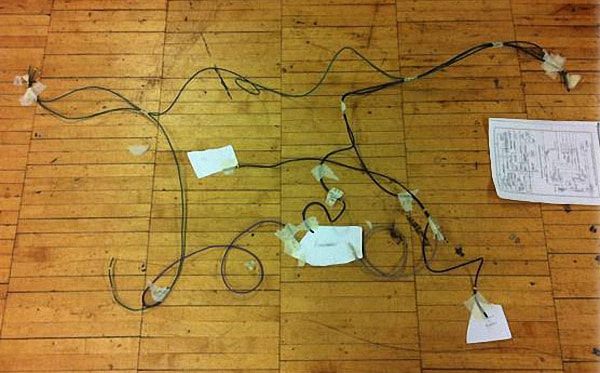
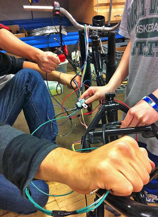
One of our main goals as the electrical team was to build a wire harness for our bike, as the wire harness that came with our bike was not compatible with an energy transfer system. Therefore, we had to build one from scratch.
To start, we first consulted the manual for a good approximation of the wiring of the harness and although very helpful, we didn’t follow the manual exactly. For example, we felt certain single snap connectors were not needed. Also, the manual didn’t fit all of our needs, as we had a speedometer, etc.
With the circuit diagram in hand, we got to work. Work involved meticulously soldering of electrical contacts on to the end of wires in order to ensure a strong electrical connection and repeatedly making sure the current flowed the way we wanted through the harness.
|
|
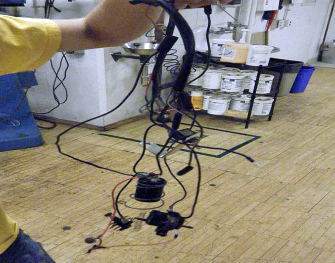
Finally, after we constructed the wire harness, we bundled it up and fastened it into the shape of an actual motorcycle:
Our Involvement with the Carburettor
The carburettor was in good shape and there was not much needing to be done. For this reason, the main work consisted of just cleaning it.
Although we did not do much reparation, we were still able to learn a lot about its form and function, especially the way it contributes to a smooth ride.
The carburettor was in good shape and there was not much needing to be done. For this reason, the main work consisted of just cleaning it.
Although we did not do much reparation, we were still able to learn a lot about its form and function, especially the way it contributes to a smooth ride.
Wheels and Brakes
Our motorcycle uses drum brakes, each of which consists of two brake shoes lined with a high friction material on a shoe plate. The shoes are secured with two springs and are separated by a pivot on one end and by a cam on the other. The cam can be turned, which will force the brake shoes to spread out to the edge of the drum and cause the bike to brake by stopping the drum from spinning.
As a result of this contact, there will be a large amount of friction between the shoes and the drum causing the wheel to stop turning and the bike to stop.
The drum brakes are connected to the brake lever on the handlebars by a cable which should be able to move about an inch before the shoes hit the drum and cause the bike to stop.
|
|
|
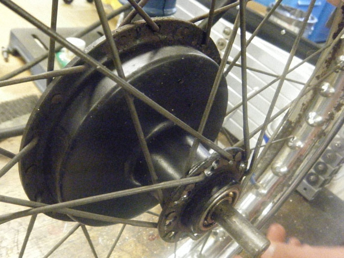
Drum brakes are beneficial to bikes because of their simplicity. However, they are not very efficient and are quite large.
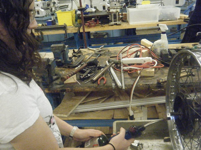
The hub contains our drum brake, as well as the spindle and bearings of the wheel. The hub is also the central part of the wheel, as the spokes come together to attach at the hub. Because we were having problems removing the wheel bearings, Elana is using a fire torch to heat up the hub. The heat expanded the housing and allowed us, with some extra elbow-grease, to remove the bearings and clean them out. |
|
The Tires
One of the most challenging parts of our maintenance on the wheels was taking the tires off of the rims. This required several people, hand soap to lessen the friction, and tire irons. Eventually we had to resort to a band saw to cut away the tire. It is very important to not damage the rim when removing the tire, so we used a hack saw to carefully cut the steel banding. |
|
The Spokes and the Rim
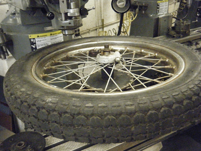
The wheel would collapse without the tension provided by the spokes. When the wheel is turning, the top spokes are providing tension and holding up the drum. Correct and equal tension within the spokes creates stability and because of this, it is important to occasionally monitor the tension of the spokes.
The process of correcting any imbalance in a rim (due to a dent, loss of tension of some spokes, etc.) is also known as “truing” the wheel.
The use of the calipers gave us proper analysis of where the highs and lows of the rim were and to fix the differentials, we tightened and loosened spokes on opposite sides of the rim in sets of four (every spoke is a part of a group of four, and they should all be tightened or loosened together, but often in differing amounts).
The loosening and tightening of spokes can be done with a spoke wrench. In our case, we had no spoke wrench that worked with the Tiger Cub, so we made our own.
|
|
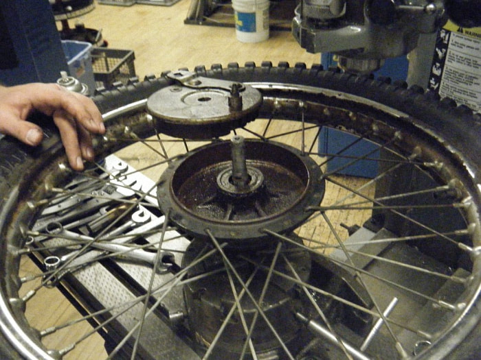
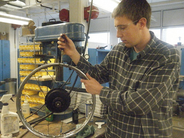
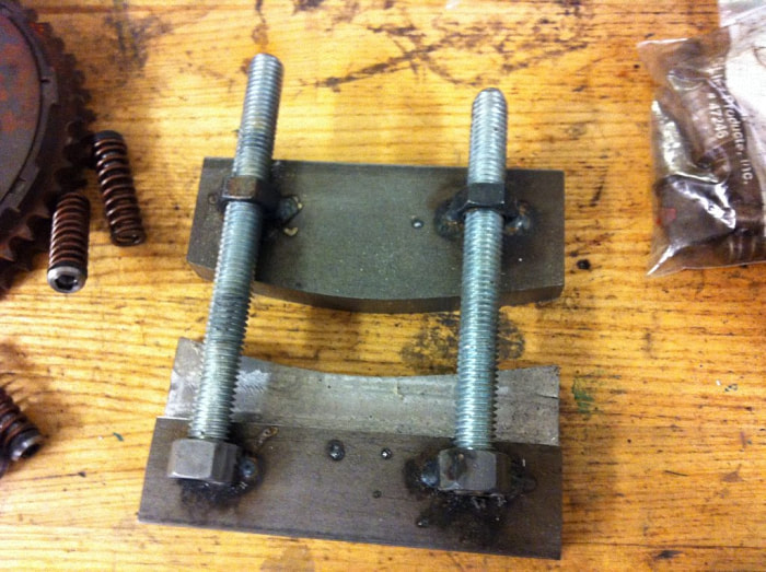
Mike here is removing the spokes and as they were removed, the hub fell to one side of the wheel due to the unevenness of tension. Another issue of unevenness occurred due to the condition of the rim. It had a large dent in it and we created a new tool specific for the bike.
This tool clamps both the top and bottom to inner and outer part of the rim. Tightening it will even out the dent into the more ideal shape for the rim and after doing this a couple of times, the rim actually improved to the point we were able to move toward finalizing our truing process. We learned to listen to every spoke and ensure it makes a ringing, and not hollow-sounding, noise.
This tool clamps both the top and bottom to inner and outer part of the rim. Tightening it will even out the dent into the more ideal shape for the rim and after doing this a couple of times, the rim actually improved to the point we were able to move toward finalizing our truing process. We learned to listen to every spoke and ensure it makes a ringing, and not hollow-sounding, noise.
The Top End
Jesse, Adam, PJ and Jess
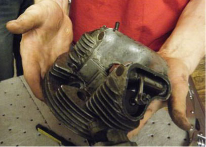
The Top End group got right to work, even before the groups were officially decided. On the very first day of class we took off the carburettor and the valve covers, then pulled the engine out.
Jesse, Adam, PJ and Jess
The Top End group got right to work, even before the groups were officially decided. On the very first day of class we took off the carburettor and the valve covers, then pulled the engine out.
|
|
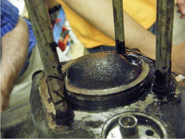
After that we removed the head and the barrel from the rest of the engine assembly. We took apart the valve assembly in the head, carefully bagging and labelling the parts.
Many of the parts were dirty and rusty, so we cleaned the accumulated grease and debris off of them in the parts cleaner. We removed the spark plug, the rocker arms, valves and valve springs.
Many of the parts were dirty and rusty, so we cleaned the accumulated grease and debris off of them in the parts cleaner. We removed the spark plug, the rocker arms, valves and valve springs.
|
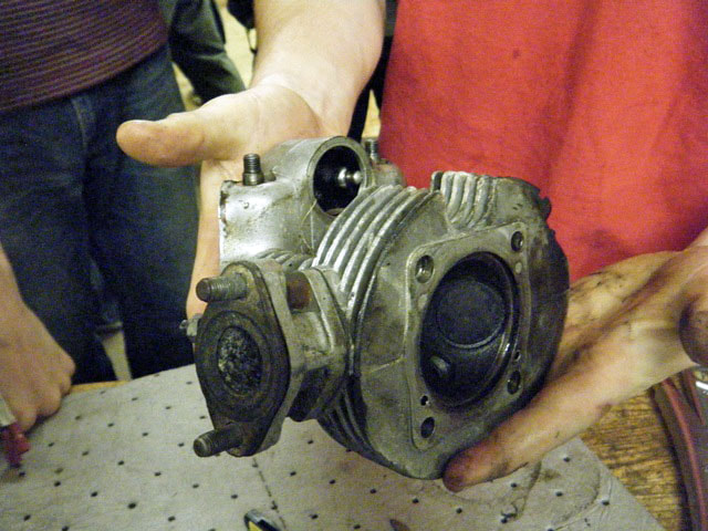
After disassembling the head, we sealed off the ports with masking tape and then cleaned the head in the glass beader.
We also lapped a mismatched joint in the exhaust port with Professor Littman and ground and cut the valve orifices for a perfect fit. The valves inside the head control in influx and outflow of fuel and exhaust. Levers called rocker arms push the valves down to open them, and springs return them to their closed position. The valves need to have a perfect connection with the seats or else the engine will have poor compression. The seats should have three matching faces of 30°, 45°, and 60°. |
|
|
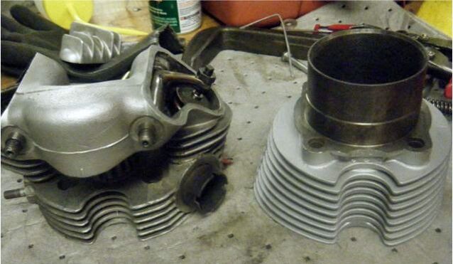
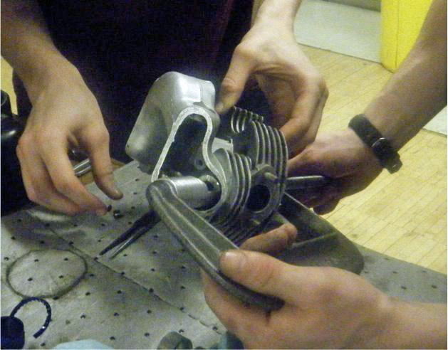
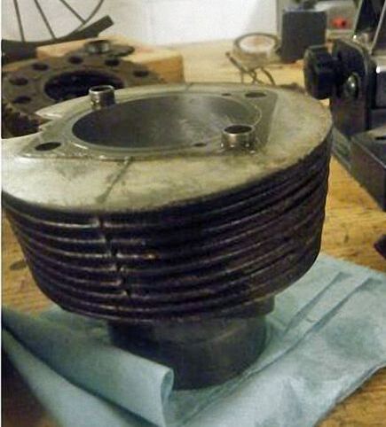
Barrel restoration
As the barrel is a single piece of cast iron, there was very little disassembly involved. Four large studs locate the barrel to the engine case and there was nothing more to do than pull the barrel off them. On a side note, we learned that although cast iron is quite porous, it is also very brittle and if you bend it in a certain way it can break easily. This happened with one of our piston rings which was also made from cast iron. Like the cylinder head, the barrel has numerous fins to dissipate the heat generated during combustion. Over the course of millions of revolutions of the engine, the piston wears the front and back sides of the cylinder, making the cylinder oval instead of circular. This becomes a serious problem preventing the engine from running smoothly because the piston loses its seal against the sides of the cylinder allowing the pressure from the explosion to leak past the piston instead of moving it. After much measurement, we determined that although the cylinder was actually quite close to cylindrical (in the best condition of all the previous Tiger Cubs) it would need to be bored from 30 thousandths-of-an-inch over its original specification to 40 thousandths over specs. The most important task of the top end restoration was to re-bore the cylinder. Glenn had built an aluminum jig that allowed us to put the barrel on the lathe, so we were able to bore and hone the cylinder on there. The barrel was dirty and corroded, so we cleaned it thoroughly in the parts cleaner. Then we taped it up and glass-beaded it to get more grime off. Finally we painted it silver with a high temperature paint to help protect it against future corrosion and to match the shiny engine head. Pictured below, these are our final products: the engine head and barrel, cleaned, repainted, and in good working order. Not pictured are the impressive Princeton ’15 aluminum valve covers that PJ designed on ProEngineer and we produced on the CNC milling machine. |
|