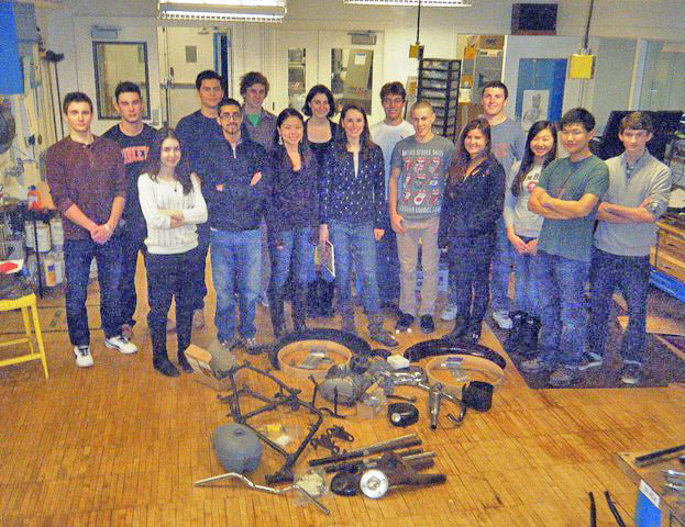
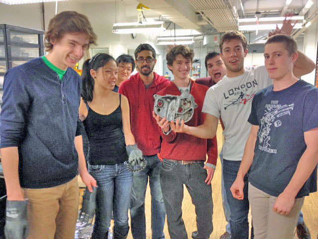
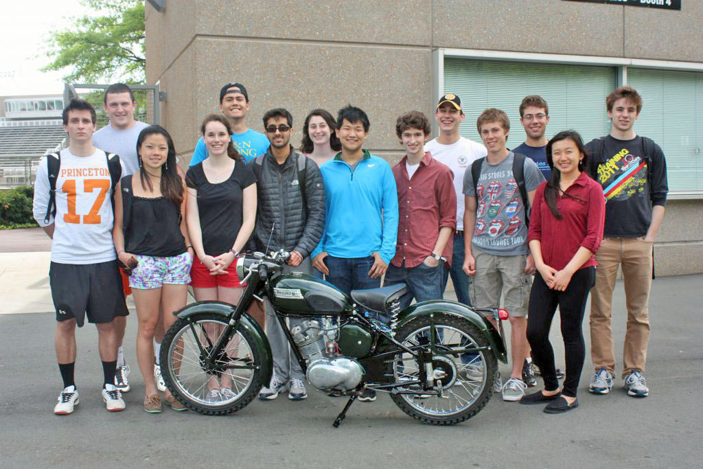
The Class of 2013 - 2014
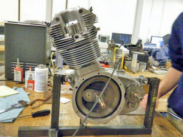
Project - 1956 Terrier with 1958 Cub motor
Project - 1956 Terrier with 1958 Cub motor
“[Practical know how] can’t be downloaded, it can only be lived.”
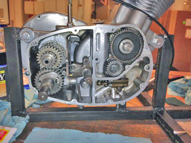
Bottom End of the Triumph ’56 Terrier - Overview Of The Oil Delivery System
A few weeks ago, our group conducted a test to ensure that the oil pump assembly was working properly. The test consisted of stripping the engine case of parts except for the oil pump and oil line, and inserting a mock distributor, which was attached to a power drill.
The drill spun the distributor, which in turn powered the oil pump. Oil was then inserted through the input oil line. A positive test occurred if the oil was sucked through the pump efficiently.
The first few tests were unsuccessful. This was because the interior of the oil pump was dirty, clogging one of the ball bearings. We disassembled the entire oil assembly, cleaned it, and then rebuilt it.
After this the test was successful.
The pump has two pistons, one large and one small. The smaller is the feed plunger, and oil goes from the oil tank to the feed plunger, initially pressurized by gravity alone. The feed plunger’s smaller area means that it pumps a smaller volume of oil. However, it pumps at a higher pressure than the larger piston. This is because pressure = force/ area, so reducing the area increases the pressure.
The scavenge plunger pumps oil from below the scavenge filter, which is below the crank, and then goes through the pump and back up to the oil tank. The scavenge plunger is larger because it’s primary purpose is to pump out all the oil that it can. Having a larger diameter cylinder results in a greater volume of oil pumped, but at the cost of lower pressure. However, the force only needs to be high enough to pump the oil to the oil tank.
A few weeks ago, our group conducted a test to ensure that the oil pump assembly was working properly. The test consisted of stripping the engine case of parts except for the oil pump and oil line, and inserting a mock distributor, which was attached to a power drill.
The drill spun the distributor, which in turn powered the oil pump. Oil was then inserted through the input oil line. A positive test occurred if the oil was sucked through the pump efficiently.
The first few tests were unsuccessful. This was because the interior of the oil pump was dirty, clogging one of the ball bearings. We disassembled the entire oil assembly, cleaned it, and then rebuilt it.
After this the test was successful.
- Larger cylinder displaces 4.6 mm, and its diameter is 7.9 mm
- volume displaced per oscillation: (PI*(7.9/2)2)*4.6 = 240.1812 mm3
- Smaller cylinder displaces 5 mm, and its diameter is 6.3 mm
- volume displaced per oscillation: (PI*(6.3/2)2)*5.0 = 155.862
- 6000RPM
The pump has two pistons, one large and one small. The smaller is the feed plunger, and oil goes from the oil tank to the feed plunger, initially pressurized by gravity alone. The feed plunger’s smaller area means that it pumps a smaller volume of oil. However, it pumps at a higher pressure than the larger piston. This is because pressure = force/ area, so reducing the area increases the pressure.
The scavenge plunger pumps oil from below the scavenge filter, which is below the crank, and then goes through the pump and back up to the oil tank. The scavenge plunger is larger because it’s primary purpose is to pump out all the oil that it can. Having a larger diameter cylinder results in a greater volume of oil pumped, but at the cost of lower pressure. However, the force only needs to be high enough to pump the oil to the oil tank.
|
Top End
We began by taking apart the head, which required disassembling the intake and exhaust valves and then taking inventory of the parts. Using a telescoping gauge and a micrometer, we took measurements of the bore and the shaft, according to the specifications from the Triumph Motorcycle Manual. From these measurements, we found that a piston which was 60 thousandths of an inch larger than the specs would fit perfectly inside of the bore to fit together to meet the specifications of the manual. Ideally, the space between the circumference of the piston head and the inside of the barrel is no greater than the thickness of three pieces of paper. |
Meanwhile, Glenn 3-D printed a rapid prototype of a throat to connect the carburetor to the head. We learned that the stoichiometric ratio of air to fuel necessary for combustion is 14.7:1
We also used the ultrasonic parts cleaner to clean the intake and exhaust springs and washers. We then went on to measure the spring constant for each of these springs.
We also used the ultrasonic parts cleaner to clean the intake and exhaust springs and washers. We then went on to measure the spring constant for each of these springs.
|
As you can see, the spring constant on the exhaust valve is slightly less than the intake valve.
We used the milling machine to compress the ring force gauge with the springs on top. From there, we increased the force in increments of five pounds, and measure the change in length for every increment. The calculated average spring constant, along with the rest of the data is in the table. |
Special thanks to Nigel for his insight and knowledge which helped us greatly in understanding the mechanics of the top end and engine as a whole!!
We recently completed sandblasting the head. From there we ground the valves using a lathe and grinding wheel and re-cut the seats on the newly sandblasted head.
We recently completed sandblasting the head. From there we ground the valves using a lathe and grinding wheel and re-cut the seats on the newly sandblasted head.
Gaskets & Creo - Cad In Motorcycle Restoring
by MGM
Gaskets, in the case of our motorcycle, are seals that are placed between the metallic surfaces of the engine so as to prevent oil from leaking. They are generally disposable, so we make our own so that they might last longer and be of a desired quality.
By working on Creo Parametric 2.0, CAD software, gaskets were created to exactly fit the dimensions of our motorcycle’s crankcase. First, the holes for the bolts on the crankcase were each assigned an (x, y) position on a coordinate system, so that they could be arranged in the coordinate plane in Creo. Then, their diameter and the width of the metal were all taken and used to give dimension to the gasket.
Finally, after many adjustments to accommodate the exact shape of the crankcase, the gaskets are ready to print. Two were made.
Transmission
Ben And Kirk
Ben And Kirk
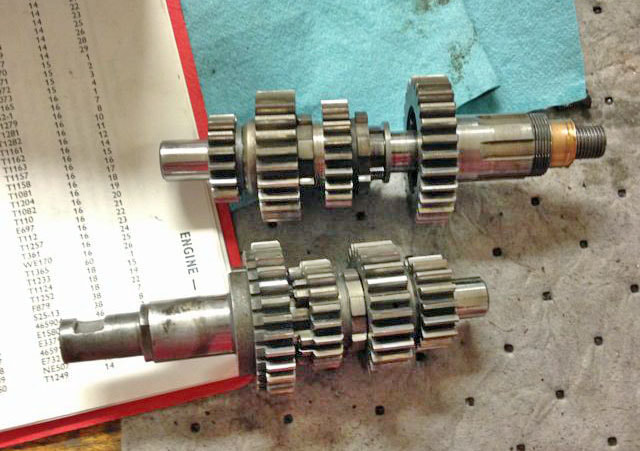
Roles of the transmission:
- – Allow you to stay in the power band at a wide range of speeds
- – Provide a gear reduction, so wheel speed is slower than engine speed
|
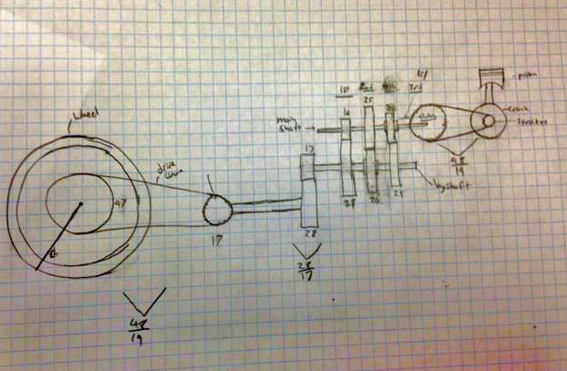
This diagram shows how rotational motion of the crankshaft, which is spun by the piston, is transferred to the spinning motion of the wheel.
At each stage of the transferal of rotational energy, the a gear reduction is used to change the rapid speed of the crank to the much slower speed of the wheel. The number of teeth can be used to determine the ratio of number of rotations of one gear per number of rotations of the other per unit of time. |
This graph represents the gear ratios in the format of engine RPM vs miles per hour of the motorcycle.
Electrical - Spark Advance Mechanism
by Daniel and Manbir
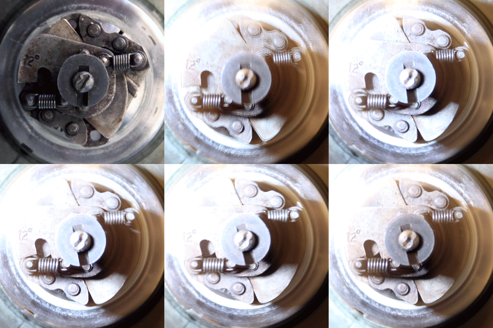
The spark advance is a mechanism in the electrical system which adjusts spark timing in the engine, adjusted based on RPM, in order to get the most efficient combustion.
The spark advance uses spring force and centripetal force, attained through rotating weights, to contract the spark advance gap and adjust the timing. Improper timing could cause engine damage among many issues.
|
The advance happens between 0 and 2000 RPM.
For this reason in order to capture the contraction of the mechanism, we would need either a high speed camera or the ability to slow down the apparent motion. The latter was the approach we chose. In order to make the motion appear slower, we used a strobe light whose pulse speed was half that of the rotation speed of the spark advance. This allowed us to effectively capture the spark advance at one place in its motion. This is because as it was flashing, the frequency of the pulses and the rotation acted deconstructively bringing the image of the spark advance to a halt. Images were captured at rotation speeds from approximately 3000 RPM to 200 RPM in 100 RPM increments. |
Frames, Forks and Wheels
by Haydn, Adam, Emma, Eliza, Hilary
Emma and Eliza - When we started, the fenders were painted but in rough shape. Both of them had rust on their surface, and needed work. First, we used Scotch Brite to get the rust off and scuff up the existing paint so that the primer would stick. After that we did the same thing but with dry sandpaper. Then, we used wet sandpaper of a finer grain.
The wet sanding allows the dust particles to remain in suspension so that they don’t stick to the fender. Then we used a heat gun to dry the fenders before priming. We did a few thin coats of primer in order to avoid drips. We finished priming the fenders (and suspension forks) and are now waiting to take them to the paint shop.
Haydn, Hilary, and Adam - We started out in different areas, but ultimately accomplishing many of the same things. Most of our jobs included monotonous cleaning of different frame-related pieces with machines such as the sandblaster and parts cleaner. Main pieces that were sandblasted include the nacelle, hubs, gas tank, forks along with other small pieces.
Haydn spent a lot of time de-spoking one of the hubs from an old wheel to salvage the hub. This was made harder by the condition of the wheel and our lack of a spoke wrench.
We also applied bond-O to the gas tank and nacelle to smooth out and solidify their structure.
After lots of hand sanding and priming both pieces are coming along nicely.
Wheels and Spokes - Disassembling
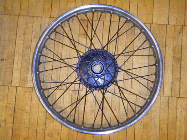
We began with two wheels that were extremely worn out and had rusted spokes. We wanted to use the hub from the wheels though, so we had to de-spoke the entire thing in order to get the hub out.
We bought entirely new spokes and rims.
We began with two wheels that were extremely worn out and had rusted spokes. We wanted to use the hub from the wheels though, so we had to de-spoke the entire thing in order to get the hub out.
We bought entirely new spokes and rims.
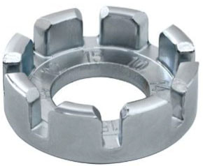
One problem we had with de-spoking and re-spoking was that the spoke wrenches we have aren’t the right size for the nipples on the spokes for this bike. It made tightening and loosening everything a little bit challenging.
|
Reassembling
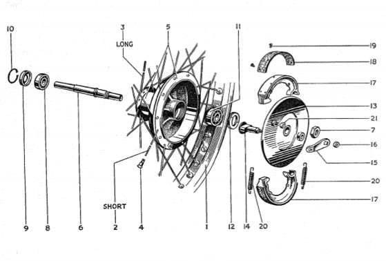
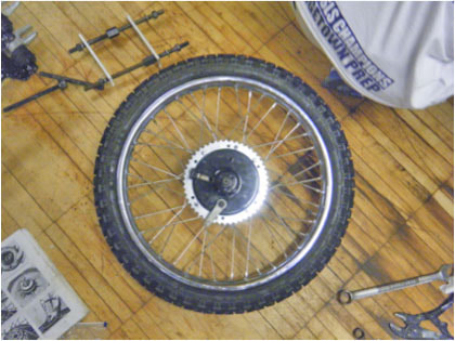
Before we started lacing the spokes on the hub, we had to assemble the rest of the wheel. First we greased the axle and packed the ball bearings with grease in order to ensure smooth motion so that the wheels would turn properly. It was important to have clean, uncontaminated grease without any grit that might get stuck in the ball bearing or on the axle. Then we had to carefully assemble the parts, except the brakes, in the hub. |
A problem we did have was that when we put the ball bearing in on the rear wheel, we accidentally did not have it lined up perfectly. It was slightly tilted, so that when we tried to put the wheel on the bike and spin it, it would get stuck. We had to hammer the ball bearing out and set it carefully back in.
|
Lacing the Wheel
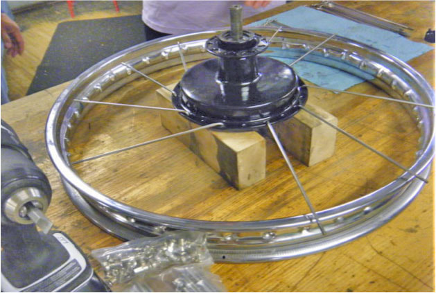
Here you can see one type of spoke lined up in the proper holes on the rim. The first step in lacing the wheel, is making sure all of the spokes are attached to the hub and the rim in the right places. There are two sizes of spokes: one size attaches to one side of the hub and the other attaches to the other. On each side, the spokes go in two different directions (cross each other). This means there are four orientations of spokes. We did one orientation at a time to put the spokes in every fourth hole on the rim. When we first put the spokes in, we only tightened them enough so that they wouldn’t fall out. |
Putting the spokes in the right holes is challenging just because they all look the same. We had to take them out and put them back in a few times before we got it right.
|
Truing and Tuning
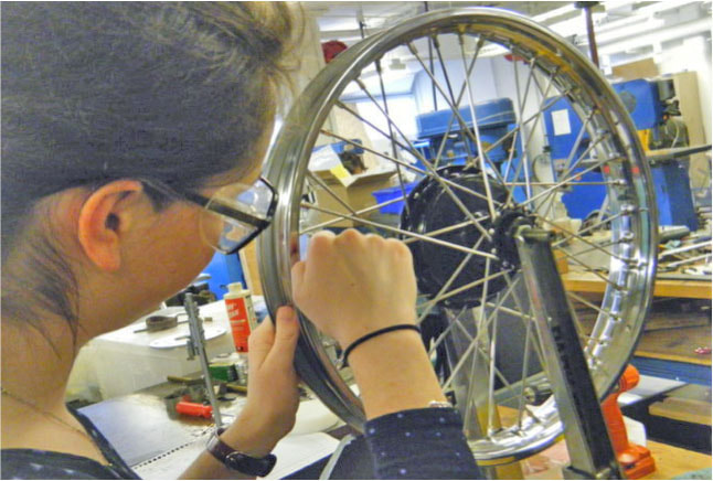
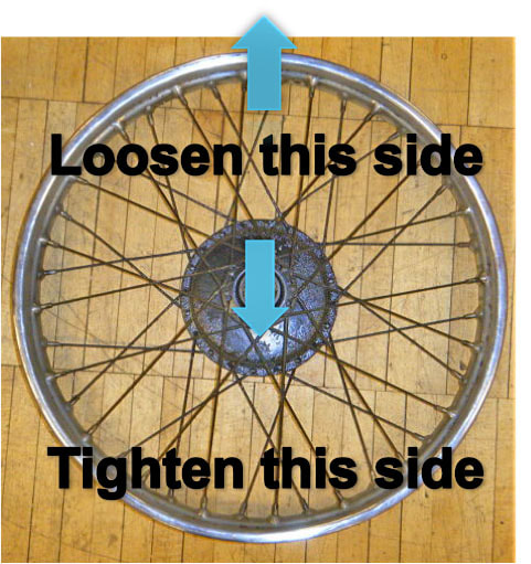
Once the spokes were tightened almost all the way, we had to start truing the wheel. Even though the spokes have all been tightened the same amount, theoretically, there can still be a good amount of wobbling, which comes from the rim and the hub not being perfectly aligned. The hub and rim might not be parallel with one another or the hub might not be perfectly centered in the wheel. Side to Side motion The first of these two problems with alignment involves side to side motion. If the rim is too far to the right over a certain area (it wobbles), then you want to loosen the spokes on the right over that area and tighten the spokes on the left. This will pull the hub farther to the right consequently moving the rim to the left. |
|
Concentricity
The second problem of alignment deals with concentricity. This means the hub is not completely centered, so the wheel rotates in concentric circles rather than in one circle. If you tighten the bottom spokes and loosen the top spokes the hub will move down and the rim will move up. The important part of truing the wheel is making sure you alternate between both types of problems. Just because it is perfect side to side, does not mean it is perfect concentrically. In order to get it within the 1/32 (ideally less) of an inch boundary, you have to do both many times. The final step in the process is tuning the wheel. This just means going through each spoke and hitting it with something and making sure it sounds clear. If there is any vibration in the tone of the spoke, it means that the spoke isn’t tight enough. Ideally, spokes of the same type would vibrate at the same pitch, but concentricity and side to side motion are far more important. Really tuning is mostly to make sure that they are tight enough. |
Wheel Offset
One thing to remember when tightening the spokes on the rear wheel is the wheel offset.
Because the chain attaches to the sprocket on the rear wheel, it is important that the hub is just the right distance from the rim or else it won’t fit when you try to put the bike together.
We created a tool to measure this offset before we tightened the wheels.
|
Putting it all together
Once the wheels were trued and tuned we had to put the rubber tire onto the rims. First we put on a rubber liner, then we wrestled the rubber tire on, and finally we put in the tube. The challenging part of putting the tube in is that it can rip or puncture easily. One of two things can happen. Either the tube can get pinched between the rim and tire, or the tube can get punctured on one of the spokes (they stick out from the rim). When one of our tubes had a hole, it turned out to be from pinching, which was good because that meant we didn’t have to grind down the end of the spokes. |

