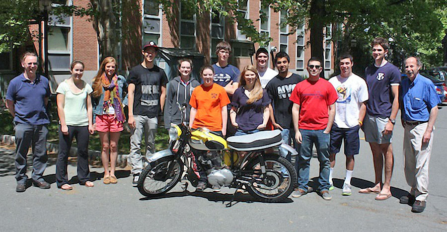
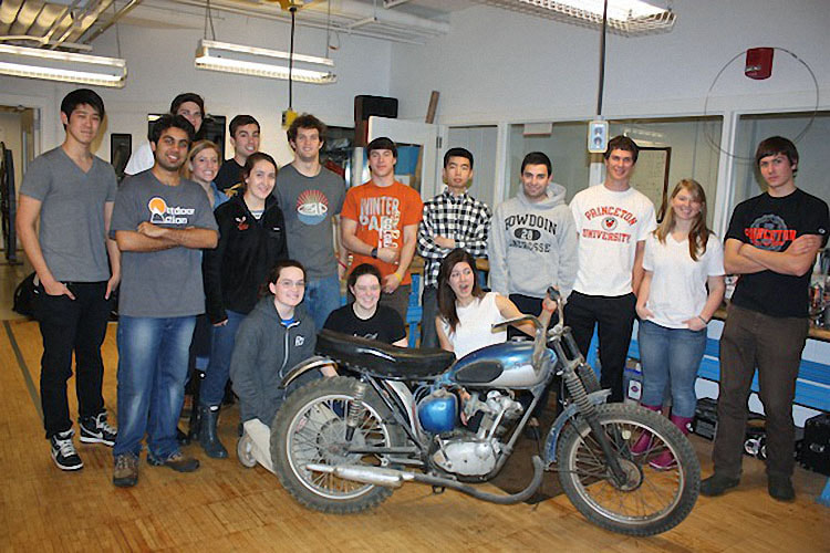
The Class of 2010 - 2011
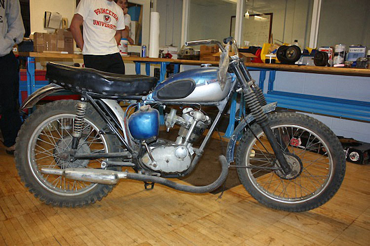
Project - 1963 Tiger Cub
Project - 1963 Tiger Cub
|
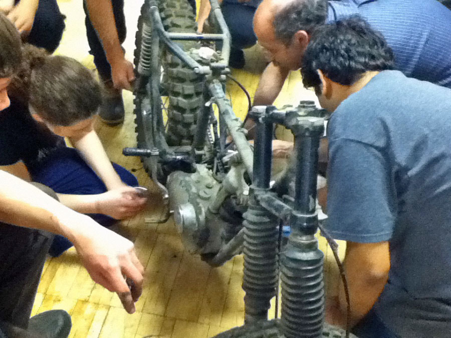
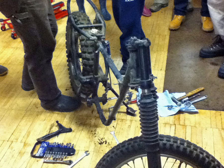
“Old bikes don’t flatter you, they educate you” Taking apart the engine was very helpful to our group for learning about how the transmission works. Most of us had never participated in a dismantling of an engine; so we learned directly how to take apart and rebuild this engine. When a group of new motorcycle mechanics takes apart, refinishes, and puts back together a bike for the first time, they are bound to have made a few mistakes. Parts and processes then must be double and triple checked to be able to determine or locate even the smallest mistake. |
In problem determination, first a hypothesis of what the problem could be and potential causes are made, then checked and tested in an attempt to solve the problem.
|
|
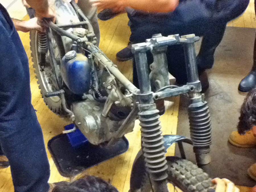
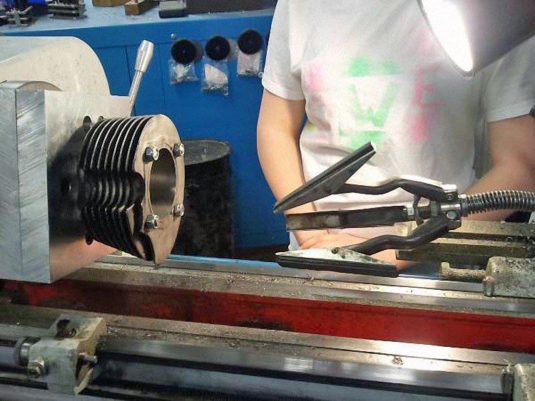
Here, the motorcycle is shown being taken apart. There was speculation as to whether the oil pump was working, since no oil was flowing into the oil tank.
|
|
|
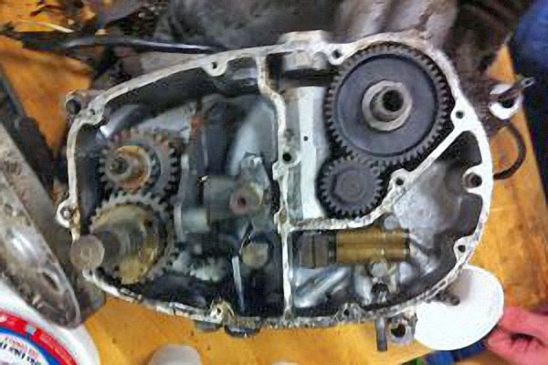
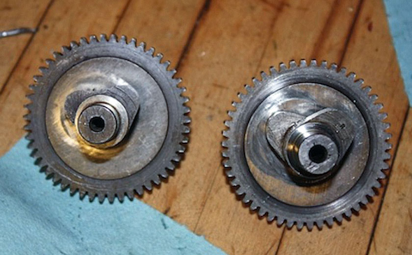
Pictured is a shot into the transmission side of the Tiger Cub engine. In the upper right quadrant is the camshaft. In the lower right quadrant we can see the oil pump. Then on the left, we can see the entire transmission mechanism, including the shifter plate, gears, and gear change quadrant. When putting back our own engine, we often referred back to pictures we had taken like this one, to help with reassembly. |
The TRANSformation
Here is the change in appearance of the transmission. Shown on the left is a picture of before we started or touched anything, and on the right is a picture of our transmission cleaned and with some worn parts replaced.
Here is the change in appearance of the transmission. Shown on the left is a picture of before we started or touched anything, and on the right is a picture of our transmission cleaned and with some worn parts replaced.
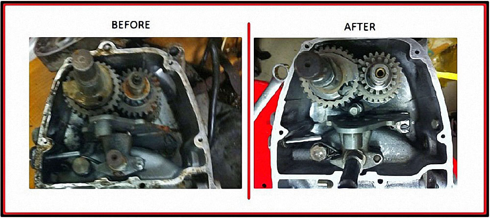
Before we started working on the transmission, the transmission was coated with a gritty grime, and much scrubbing and scraping of the parts and cover was needed to restore the transmission to “like new” condition.
Some other things we did within the transmission included making and putting in new gaskets and seals, and replacing worn parts such as the metal square that engages the kick start.
Some other things we did within the transmission included making and putting in new gaskets and seals, and replacing worn parts such as the metal square that engages the kick start.
|
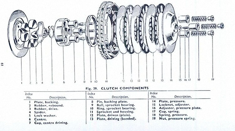
How the Clutch Works
When the clutch is engaged, the driven and driving plates are pressed together by the pressure plate and springs and spin at the same speed. When the clutch lever is pulled, the clutch operating rod pushes up on the pressure plate, disengaging the clutch and allowing the engine and transmission to spin at different speeds, thus allowing the rider to shift gears. |
|
Why does the clutch have multiple plates?
Having multiple plates increases the friction, thus reducing the slippage. The greater the friction, the greater the torque that the clutch can handle without slipping.
Having multiple plates increases the friction, thus reducing the slippage. The greater the friction, the greater the torque that the clutch can handle without slipping.
|
Technical Data - How much force is applied by the springs?
Measurements: Length of the spring = 1.53in. = .1275ft. Length of the spring after 20 lbs. of force applied = 1.324in. = .1103ft. Number of moving surfaces in contact = 7 Coefficient of friction of cork on steel = 0.8 Diameter of the clutch = 5.33in. = .444ft. Given: The clutch slips at 50 ftlbs. of torque |
Calculations:
F = kx (force on the springs) F = uN (force of friction) T = rF (torque) k = F/x k = (20lbs.)/[(1.53in.-1.32in.)(1ft./12in.)] k = (20lbs.)/[(.21in.)(1ft./12in.)] k = 1,143lbs./ft. T = rF = 50 ftlbs. = .22F F = (50ftlbs.)/(.22ft.) F = 227.27lbs. F = uN = 227.27lbs. F = 7uN F = (7)(0.8)N 227.27lbs. = 5.6N N = 40.6 lbs. Force applied by each spring = N/3 = 13.53 lbs. |
From there, we can calculate the amount of initial compression required when each spring is screwed in to generate this amount of force so that the clutch will slip at 50ftlbs. of torque.
F = kx
13.53lbs. = (1143lbs./ft.)(x)
x = .0118ft.(12in./1ft.)
x = .142in.
So given torque, we were able to find the force applied by the springs and the distance we need to compress the springs initially to generate this force. On the other hand, if we assume a certain amount of compression in the springs, we could also find any torque.
|
Cylinder
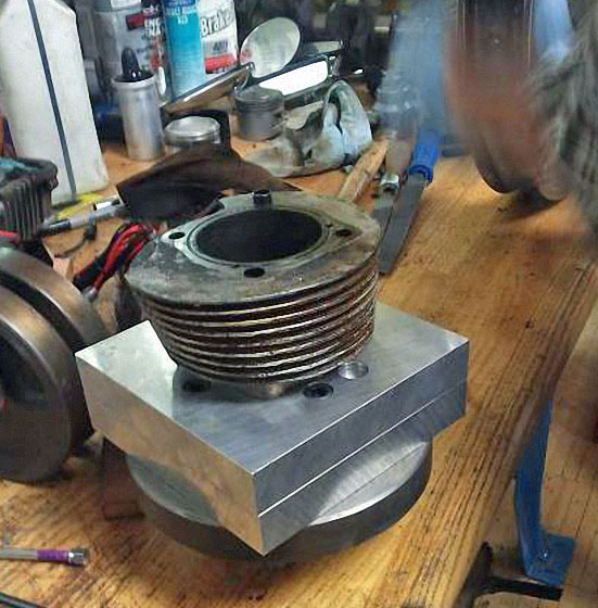
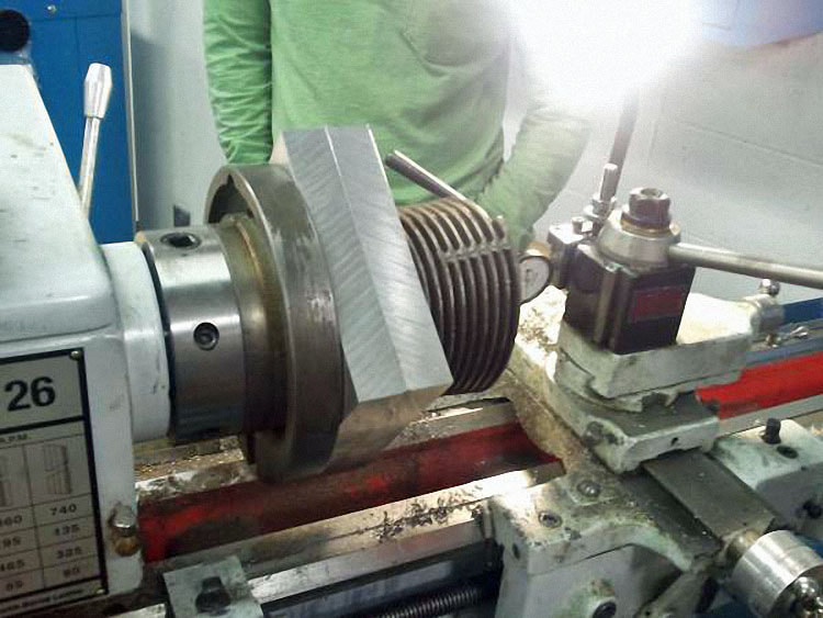
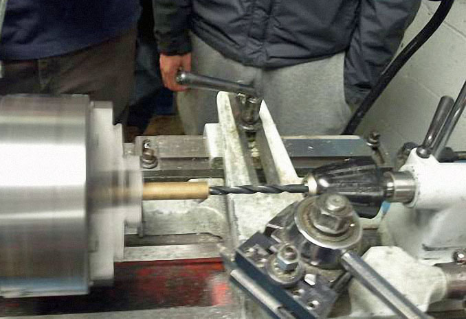
The cylinder needed to be re-bored as it was found the bore was off center and tapered as well. We decided to make it 0.060 inches over its original diameter, and ordered a new piston to fit that new size. The bore of a cylinder is a measure of its inside diameter. We bored the cylinder on the lathe, bolting it onto a custom jig using the four holes for the head bolts. The idea here is to take only a few thousandths off at a time, and advance the cutter slowly to create a uniform surface. Once the correct bore diameter is established, the cylinder wall has to be honed, which removes scratches and grooves made from the cutting tool. |
|
|
|
The honing tool is also used to create tiny vertical grooves in the cylinder wall, allowing oil to move vertically in the cylinder. If the grooves from the boring were left in oil would only move in a spiral fashion, and the cylinder would be ineffectively lubricated.
The piston rings have gaps in them for two reasons. The first is to allow room for expansion, so the rings can expand when they heat up and not bend.
The second is to allow oil to move throughout the cylinder. The tiny gap allows a miniscule amount of oil through to lubricate the walls.
Too large of a gap will decrease compression, while too small a gap can cause the rings to bend or snap, or the engine to overheat due to lack of lubrication.
Cylinder Head
We decided to make new guides with Glenn’s suggestion and used some bronze bar stock that was in the shop.
We drew up the dimensions of the old guides on Pro-Engineering, but enlarging them so we could drill a new hole for them to seat in rather than hoping they would fit nicely into the old spot, which was probably worn.
They are also longer than the old ones, and have closer tolerances, which means the valves will move more precisely.
|
We made the guides on the lathe, first making one end square. The next step was to drill the inside channel for the valves, then bring the outside down to the correct diameter. The angle cut was next and we added chamfers on both ends. The final step was cutting the groove for a ring that keeps the guides at the correct depth in the head. |
The valve seats had to be re-cut, and we decided to do a three angle valve seat. The purpose of the seat is to form a surface for the valve to seal against during the compression and combustion stroke, so that the cylinder does not lose compression.
If it does not seal, expanding gases will escape around the valves, lowering our efficiency and probably causing damage in the head.
A three angle valve seat is a popular method for higher performance engines. The idea here is to create a small, uniform ring at the correct angle to form a seal against the valve.
If the area of the seal is too large, the valve will not form a good seal. If it is too small, there will be a good seal but the metal will overheat, warping and damaging it and the valves.
The happy medium is made using three cutting tools, each with a different angle.
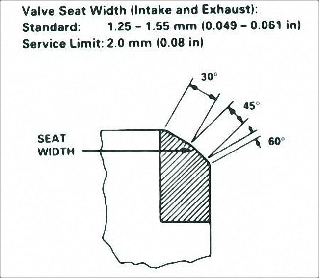
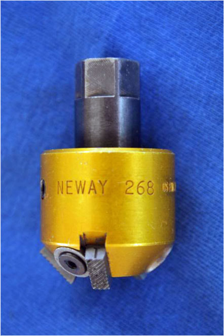
The process involved the following three cuts. The first angle we cut is around 30 degrees. This is the base cut, where most of the metal was removed.
Once we had that angle well under the valve, we cut the 45 degree angle, the mating surface. We intentionally made this surface larger than necessary, so we could bring down to exact tolerances with the 60 degree cutting tool. |
|
Once the correct seat was established, we lapped the surfaces to match exactly with the valves using a grinding compound, which was placed on the mating surface of the valve.
The valve was inserted into the correct position and spun, first by hand with coarser grit and then with a drill with fine grit.
The valve was inserted into the correct position and spun, first by hand with coarser grit and then with a drill with fine grit.
|
Camshaft
Here are two cams. The one on the left is the STANDARD CAM, the one on the right is the RACING CAM. We started using the RACING CAM, but because of the extensive valve overlap, the engine was hard to start. After the STANDARD CAM was swapped in, the bike was easy to start. |
|
|
|