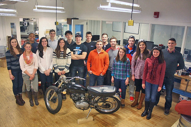
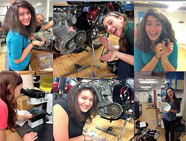
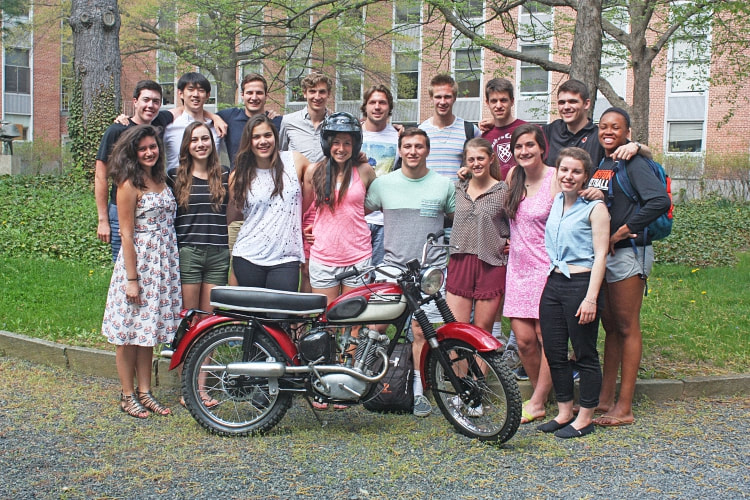
The Class of 2014 -2015
Project - 1957 Tiger Cub
Project - 1957 Tiger Cub
|
Dissembling
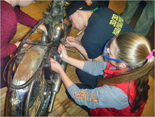
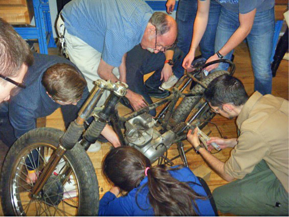
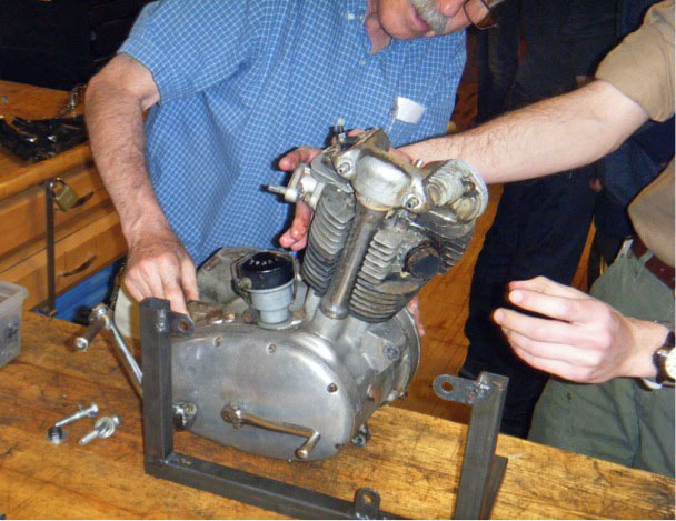
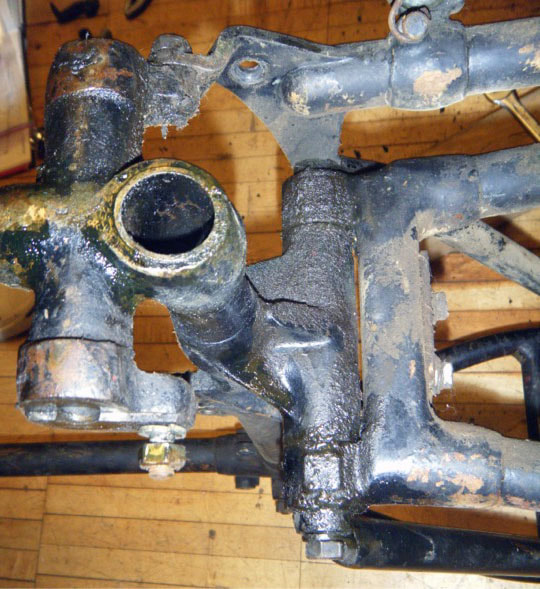
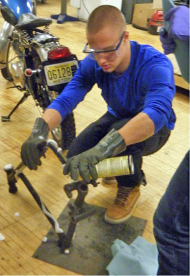
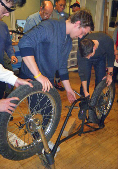
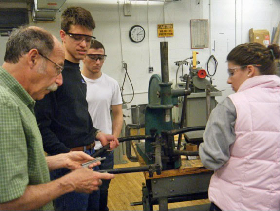
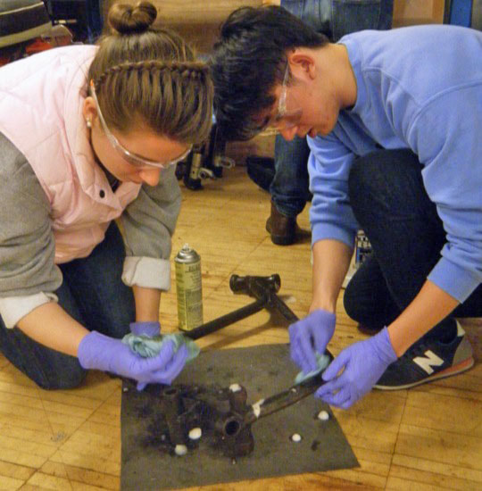
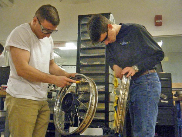
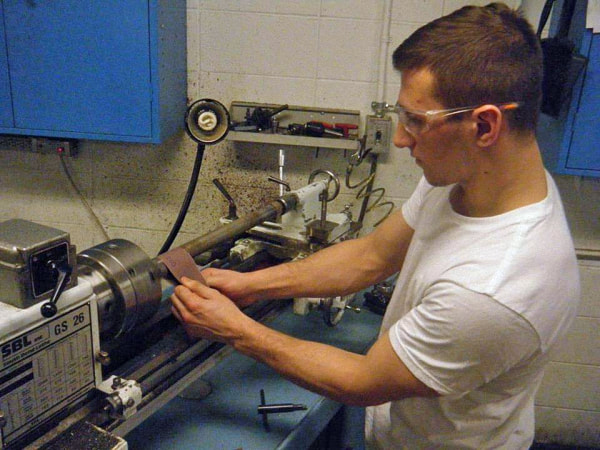
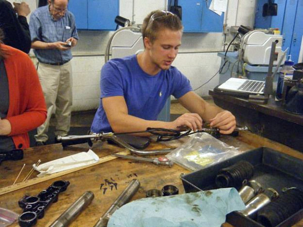
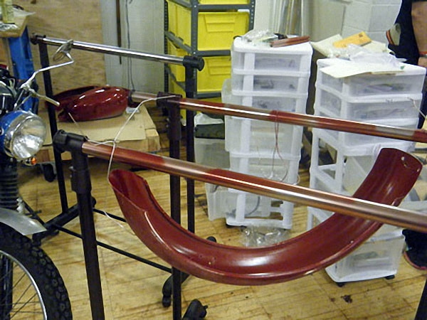
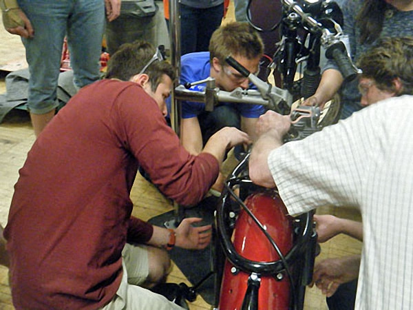
Day 1 - We started dissembling the bike and removed the engine. Then over the next three weeks, we stripped the frame with Professor Littman showing us how to use a machine to work on the frame. Many parts were extremely dirty and needed much cleaning. We then took apart the engine beginning with the top end before moving on to the bottom end. |
|
Top End
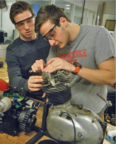
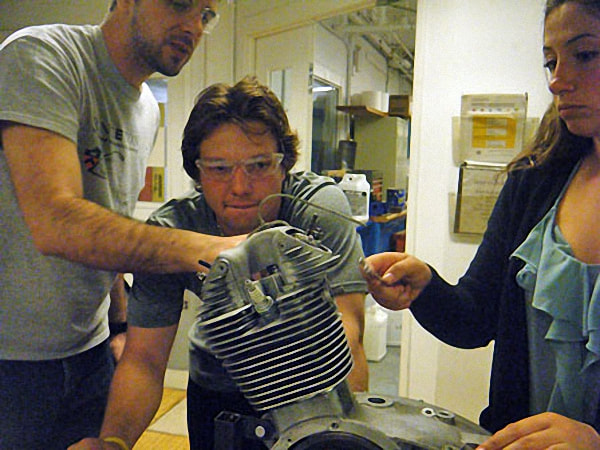
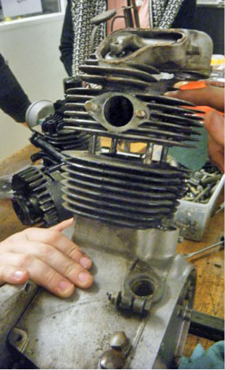
We were able to use a standard piston because the cylinder had very little wear. We had 3 one thousands of an inch of clearance between the piston and the cylinder, which is well within the manual specifications. If we were outside the specifications, we would have had to use a larger piston. Our piston was new old stock and was in the bag from 1957 with original oil on it. We had to clean that off and attach the piston to the conrod by using the wrist pin. Once we did that, we had to put the circlips in to hold the wrist pin in place and then put piston rings on. Now, we had to lower the cylinder onto the piston. It was slightly difficult to get it over the piston rings. I had to hold the cylinder and push it down while John pinched in the piston rings. However, this is a good problem to have because if the cylinder had just slid onto the piston, we would have a lot of space on the outside of the piston and lose compression. We found...
|
The process we went through with the valves was a fairly smooth one. First, we cut the valves so that they would sit correctly in the valve seats to create a seal.
Next, we lapped the valves, first with a rougher compound and then finer compound to assure that the valves would sit correctly.
Next, we checked our work to see if the valves sat correctly by using a blue compound which showed us where the valves were in contact and not in contact with the valve seats.
Lastly, we re-assembled the valves and adjusted the rocker gap to assure that the rocker arms would not be too tight while the motorcycle is in operation.
Carburetor
The carburetor on our bike was relatively complete. We took it apart, took inventory of all the parts and then took the required missing parts from other carbs that had been leftover from previous years.
Once we had all the parts, we reassembled the carb and tested it on the orange bike to ensure that it worked.
Bottom End, Clutch and Transmission
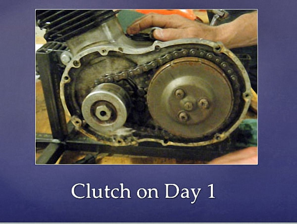
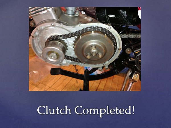
Although the clutch was in a rusty state, it did not need much repair. Therefore the majority of the work was cleaning the different parts to leave them much cleaner than when we started.
Although the clutch was in a rusty state, it did not need much repair. Therefore the majority of the work was cleaning the different parts to leave them much cleaner than when we started.
|
However we did find our mainshaft gear was rather abused and some of the gears had fused to the shaft from overheating.
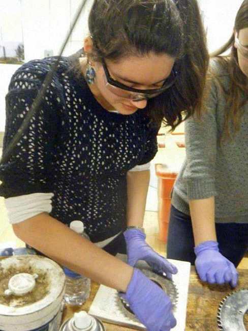
The innermost gear had also lost a tooth, which we were able to find in the case. We then analyzed it with Professor Arnold to understand why it had broken off. We began by cutting the tooth with a diamond saw, then mounted the small piece of tooth in epoxy so that it would be easier to polish. We first started with a high grit sand paper and slowly made our way down to the finest grit sandpaper, allowing us to get the smoothest, almost mirror-like finish, on the piece of tooth. We were able to see that the tooth was indeed case hardened by dropping it in acid and quickly transferring it to water to etch the surface. In that way we were able to see the different make-ups. |
We then used a Scanning Electron Microscope to see the different elements the tooth was composed of and were also able to see close up pictures of the structure of the material.
The hardening test was done to different spots of the tooth to see the different hardness's at different locations - important because it lined up with our theory that it was case-hardened.
The tooth was clearly brittle, because it broke and flew off of the machine when too much pressure was applied to a corner of the tooth.
We came to the conclusion the tooth had broken off due to an inconsistency in the metal, and that it was brittle and case hardened.
|
Fasteners and Gaskets
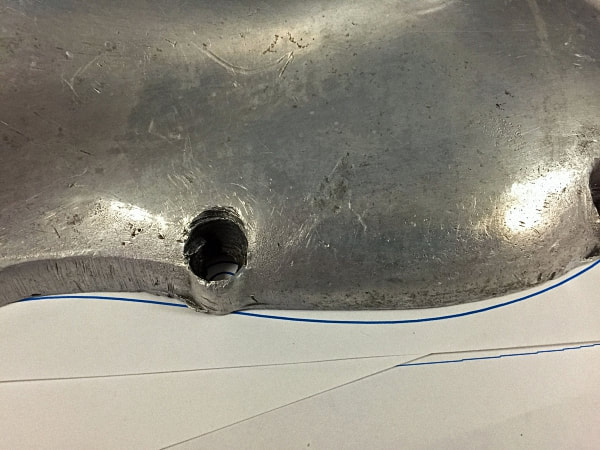
by Phil and Mark A past owner had at some point stripped the threads in some of the holes in the engine block. To “fix” this, he had screwed larger bolts into some of the original holes, messing up the threads completely, and re-tapped other holes for larger bolts. Because of using larger bolts, he had drilled out the holes in the covers and we found it was particularly bad in the inner primary cover. The holes were larger than they were designed to be, leading to cracks in the cover, some of which had been welded together at some point. In addition to all of this, most of the bolt heads were in very poor condition. |
In addition to all of this, most of the bolt heads were in very poor condition and since few of the bolts in the engine were useable, we replaced them all with new stainless bolts of the original diameter and pitch.
As we were using bolts of the original diameter, we could use a new inner primary cover, getting rid of the old cracked one.
We also wanted to use the correct size bolts in the drilled-out engine block, so had to put inserts into many of these holes. With the engine block matching the motorcycle frame, it was important that we not replace them with a different size ones.
|
Inserts
We learned that inserts can be used to put smaller fasteners in larger holes, as they decrease the diameter of holes and can also be used to change the thread pitch. Inserts also need threads to go into, so for holes with poor threads, we first drilled out the old threads then rethreaded the large hole with a tap so we could screw in the insert. Finally, we could clean up the protruding parts of the insert so that the surface would be flush. This was very important for the surfaces of the engine block, which would match the cover surfaces to prevent oil leakage. |
We used two types of insert...
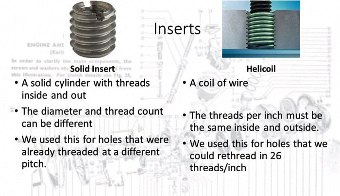
- A solid insert, which is basically a hollow cylinder with threads inside and out. The exterior threads match the threads in the larger hole, and the internal threads match the desired threads for the bolt. This can be used for changing the pitch of a hole (say from 28 to 26 threads/inch). To clean up the protruding surface, we could sand the rough edges down.
- Helicoils, which look like a spring or coil of wire with somewhat triangular wire cross-section. It also screws into a threaded hole, but, since the threading comes from the wire coil, the pitch inside has to be the same as the pitch outside, though the diameter will be smaller. We could use this for holes that were already threaded at 26 threads/inch, or holes that we had drilled out and threaded at that pitch. To finish the surface, we just had to clip off a bent piece of wire that was used to screw it in.
Gaskets - "Those fiddly bits that go between the two metal plates" - A wise mechanic
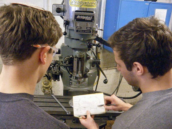
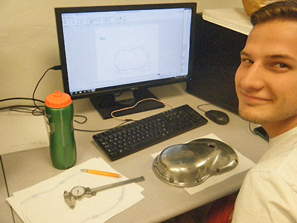
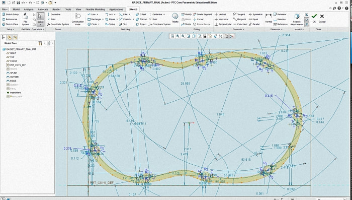
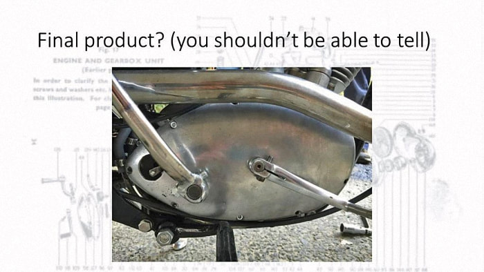
We decided to make our own gaskets out of rubberized gasket paper by using a 2D "vector" file. We used an electronic drill press to get accurate hole locations and then printed out a 'prototype' on regular paper, comparing it to the actual cover.
If this was correct, we then uploaded the file to a laser cutter for it to cut out the gaskets to the correct dimensions.
If this was correct, we then uploaded the file to a laser cutter for it to cut out the gaskets to the correct dimensions.
Electrical System
by Kate and Mun
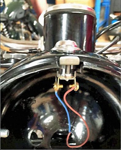
First off, we had to wire an on/off switch into the circuit of the motorcycle. When turned on, it allows the ignition system to work.
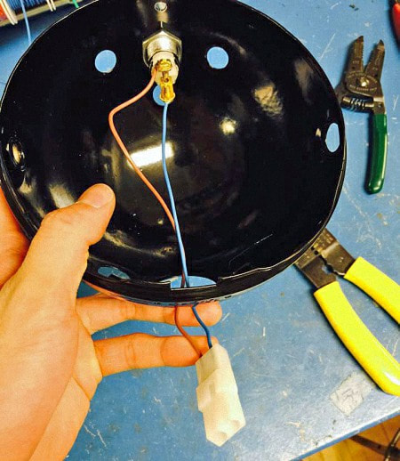
We inserted the switch into the circuitry in the headlamp using connectors to enable us to connect and disconnect it easily from the wiring harness.
This allowed for easier handling of the headlamp, since we could take it on and off at our request.
|
Points and Distributor
We faced a number of difficulties while assembling the points as well as the distributor. One problem stemmed from the fact the camshaft of the distributor actually came from an older spare part that we had lying around in the shop. We had to use this one instead of the original one due to the fact that the original had some broken parts. The camshaft we used did not have an optimal fit for the distributor casing, which warranted us to shave the sides of the camshaft in order to have it spin snugly within the whole distributor assembly. Furthermore, the points themselves needed some attention. Because we replaced the original points with new spare parts, there were bound to be some incompatibility. We had to shave some material off the lever attached to the points so that the gap between them could be rendered smaller. |
Final Rebuild
