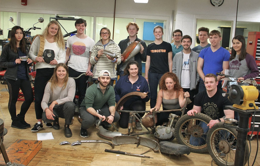
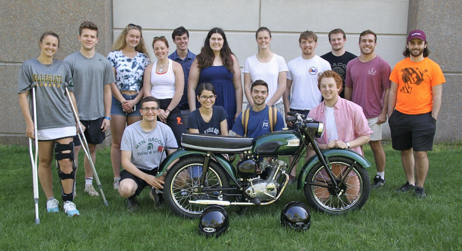
The Class of 2017 - 2018
Project - 1963-2 Tiger Cub
Project - 1963-2 Tiger Cub
|
Course Objectives:
|
Groups:
|
Shop Rules:
- Only use our class’s materials, including safety glasses
- Leave the workspace clean after class, keep spaces and tools organized
- Use machines with supervision
|
Frame and carb
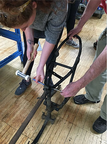
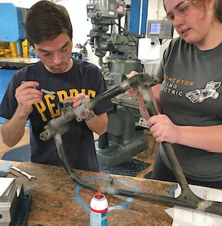
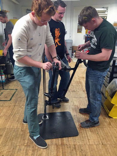
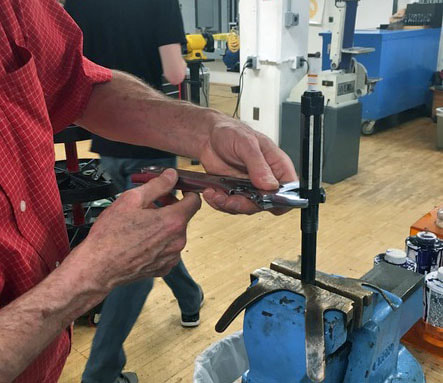
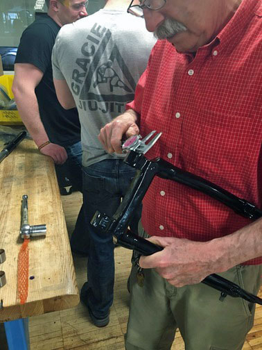
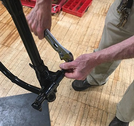
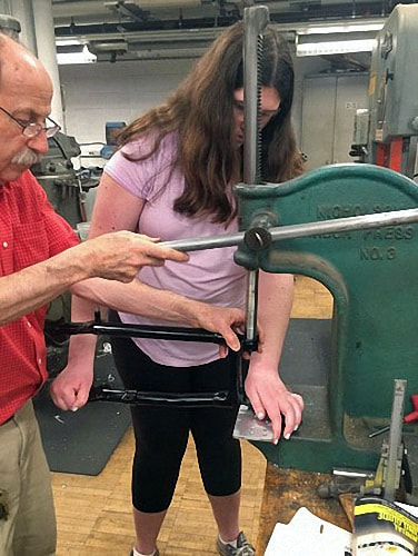
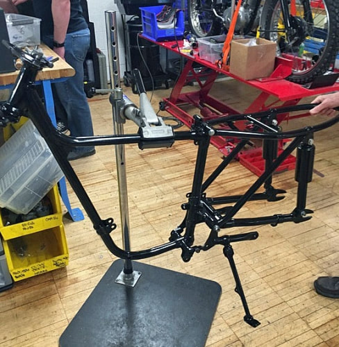
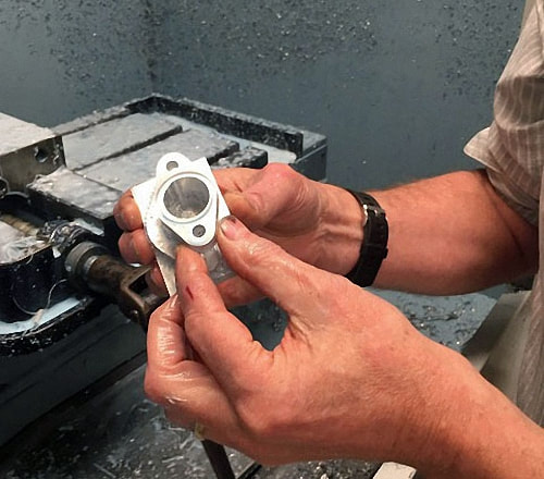
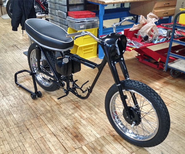
Overall - What We Did First, we worked on the frame. Our job was to assess it for weak points or cracks. We used the sand blaster to clean it then sent the parts out for powder coating and chroming. After we got them back, we worked to (re)assemble the whole frame. Second, while waiting to receive the parts back from the powder coater, we worked on the carburetor. Our job was to assemble a carburetor out of the parts we had in the shop. We had to disassemble multiple Amal carburetors, clean the parts, reassemble one and test it. Third, throughout the process we also had to fashion parts of our own. For example, we needed a manifold to attach the carburetor to the engine, so working with Glenn, we were able to manufacture one. We also had to fashion a bracket for the seat from scratch using CAD. Lastly we made a piece for the throttle cable. Fourth, our last project was to assemble the handle bars, including the break and clutch levers as well as the throttle. Later in the restoration process, after we had assembled the frame, we worked on the handle bars. Taking the parts we had from the chromer (the handlebar and the two levers, as well as the brackets for each lever), we began to put them together. We also noticed that the threads for the levers and their brackets were unique for a Triumph motorcycle in that they were 10-32, so we went to stock room to pick up some 10-32 bolts. There were a few times during our restoration when we did not have all of the parts we needed, and it was either easier or more time effective to make them ourselves. |
|
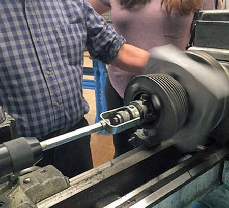
The other part we had to make was the throttle attachment piece.
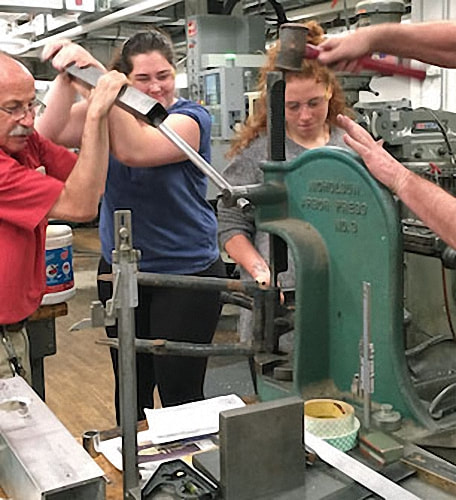
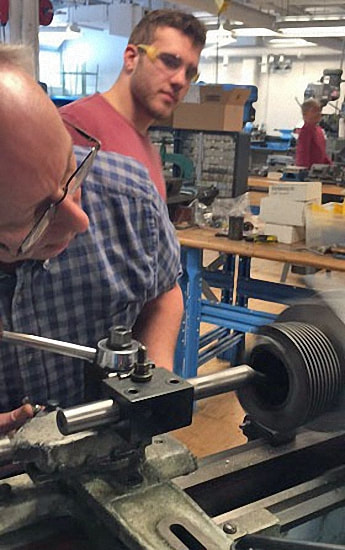
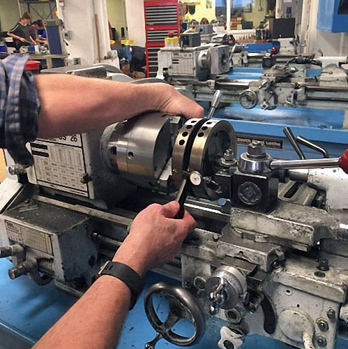
Taking measurements, we created a sketch of the part. Then Glenn helped us to use the lathe to manufacture this part. We used a hack saw to cut a slit in the piece so that it could slide over the throttle wire. |
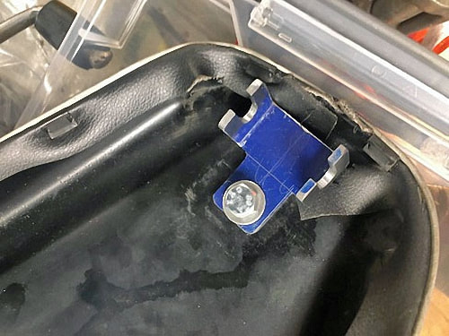
The first time this happened was when we were changing the seat of the blue motorcycle. The old seat had a bracket soldered on to it, and also had attachment holes in a different configuration than the new seat.
We designed a new bracket using calipers to take measurements, then PTC Creo to CAD the bracket we designed. We also used a similar process to design a front seat bracket for our motorcycle. |
The Carburetor
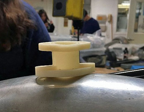
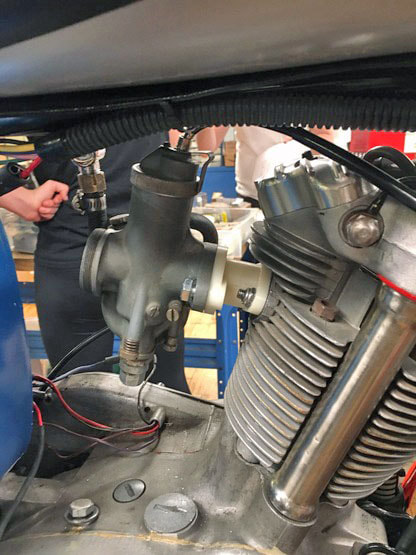
In the case of our motorcycle we used a carburetor not meant for our bike, so we had to design a new manifold in the correct configuration.
In the case of our motorcycle we used a carburetor not meant for our bike, so we had to design a new manifold in the correct configuration.
The main contribution we made to the design of the manifold was, after seeing the white trial version, telling Glenn that the angle should be increased from ten to twenty degrees.
This provided for greater clearance between the top of the carburetor and the bottom of the fuel tank. It worked perfectly.
Thank you Glenn.
To assemble the carburetor, we first had to disassemble multiple carburetors to collect all of the parts we needed. We then cleaned these parts and assembled them into the one we were going to use. Next, we had to test it for leaks. We originally were going to use gasoline to test it, but then we were told we could just use water. We filled it with water, and our carburetor did not leak! Thus, we were done with our assembly.
When we arrived at class the next day, we found that our carburetor was disgusting. Apparently, we had not drained it out enough, and the water had some sort of precipitate in it so a strange white substance was left in the carburetor.
When we tried to clean it off, we scratched off the top layer of aluminum and it oxidized with the air, turning white. This led us to believe we had not fully cleaned our carburetor, so we spent the class with carburetor cleaner attempting to clean it out completely, until we realized that we already had! Finally, we reassembled it again, tested it on the red motorcycle, and it worked!
The moral of the story is that you should use the material meant to be in the part to test it. DON’T USE WATER.
|
Top End
Our Parts:
What We Did:
|
|
Our Clutch
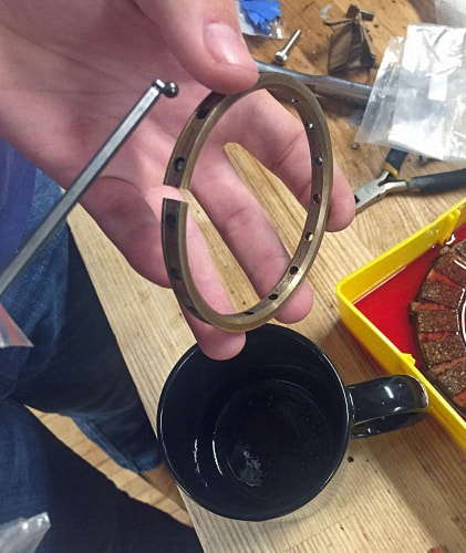
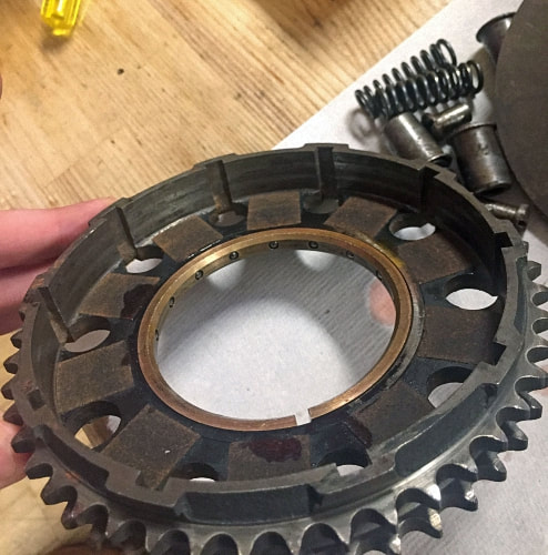
We disassembled the clutch basket and thoroughly cleaned the metal interlocking clutch plates. We replaced the worn-out cork plates with new ones. Before re-inserting the restored clutch, we made sure that all the inner materials were well-soaked in clutch fluid, which helps increase the static friction between clutch plates. We also made sure the clutch springs were tight enough as loose springs mean clutch plates slip past each other when the driver kicks the kickstarter, which can make the engine impossible to start. |
Why cork?
One last question we had was why our clutch plates used cork. In our daily lives, we almost never see cork outside of wine bottles, yet here it was in this random engine part.
Upon closer inspection, cork turns out to be an excellent material for this purpose because it has a high coefficient of friction, which determines how much force it can transmit when pushed or slid against something.
In the modern day, kevlar is frequently used as a clutch plate material because it has an even higher coefficient of static friction, and it lasts longer than cork.
Our Transmission
Our task was to take the transmission apart, clean it, inspect it for damage, and put it back together. When we examined it at first, it was not very clean.
Our task was to take the transmission apart, clean it, inspect it for damage, and put it back together. When we examined it at first, it was not very clean.
|
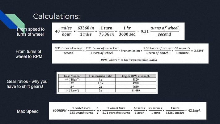
However, when we took it apart and cleaned it, we saw that it was in pretty good shape. None of the teeth on the gears were cracked, so we didn’t have to repair or replace them. There were a few parts missing, so we had to make or replace them. But overall, our transmission was in pretty good shape. Once cleaned and rebuilt transmission our looked pretty good. We did a set of calculations based on the gear ratios to see the revolutions per minute (RPM) of the engine at 40 mph in each gear, and then the maximum speed of the motorcycle based on the engine’s max RPM of 6000. You can see in the chart that in low gear, the requisite engine speed to go 40 mph quickly exceeds the engine’s maximum RPM. Shifting to high gear while you accelerate is very important! |
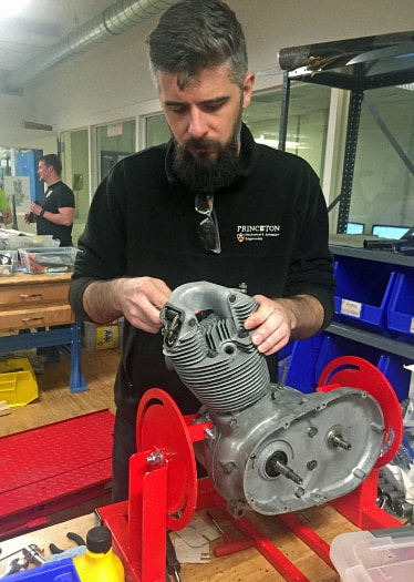
Bottom end: What We Did
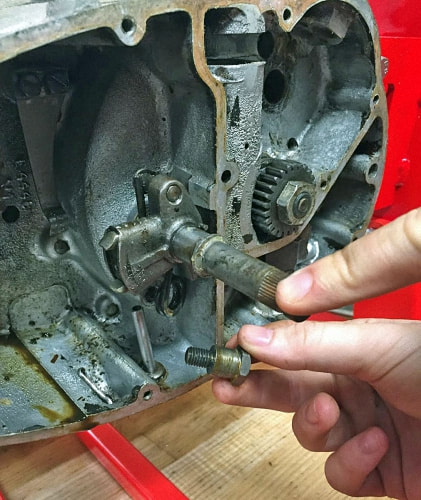
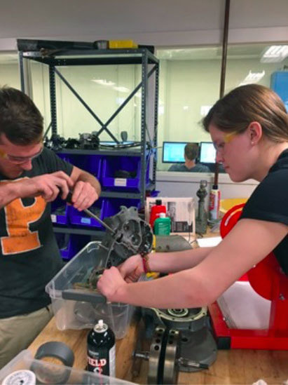
- Disassembled the bottom end entirely while carefully organizing different parts of the engine into labeled ziploc bags.
- Cleaned off all the parts.
- Partially reassembled the engine.
- Tested the oil pump by rotating the gear which is connected to the oil pump forcing oil through the engine and returning it to the oil tank.
- Finished reassembly and applied some gaskets to seal things up.
|
Wheels
We inherited the wheels from the original motorcycle and needed to take them apart. We removed the old tire, rim and spokes, and ordered new parts to replace the originals. A significant amount of force was required to take the tire off. After finally removing the tire, we cut the spokes off. In light of the significant challenges encountered with the first wheel, we decided to use a saw to cut the tire off of the second wheel, and the saw penetrated the rim! Retrospectively, it would have been a good idea to keep the parts instead of throwing them out as a reference point for measurements later in the process. We spent a few days cleaning the hubs with metal brushes and sandblasting the parts. We then sent the two hubs off to be powder coated. |
At various points, there were multiple hubs in the mix: some from previous motorcycles, some from the 1963-2 Tiger Cub. While the hubs were being processed, we cleaned up other parts including: the screws, the axles, and other hardware.
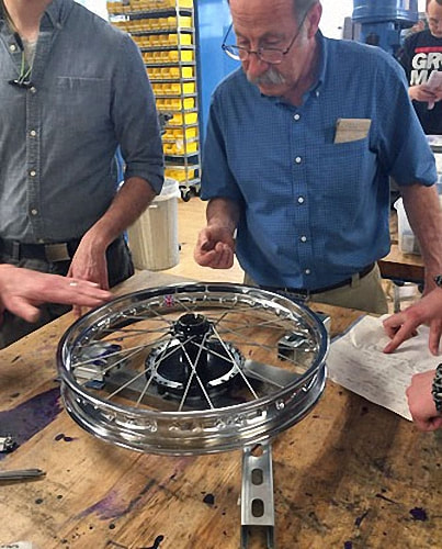
When we got the hubs back, we began to put the spokes on the wheel.
When we got the hubs back, we began to put the spokes on the wheel.
|
This was one of the more challenging parts of the assembly process. The spokes do not go out radially in a line from the center of the wheel to the rim; rather, they sit in a vector at an angle from the vector in order to distribute force and allow for compression to take place.
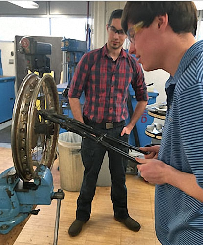
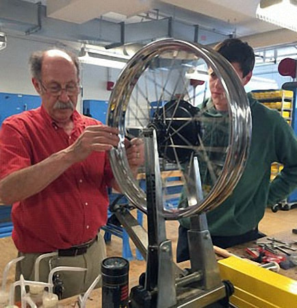
It took a number of tries to properly spoke the wheels. Bill Becker helped us with lacing the wheel, providing insightful advice on how to get the correct tension on the spokes and offset from the rim to the hub. After the spokes were properly attached to the rim, we needed to adjust for the tension and displacement. In order to accomplish this feat, we trued the wheel. We learned the art of “truing” the wheel in which we learned how to loosen and tighten the spokes to reduce the “offset”(wobbling). To mitigate horizontal displacement, we adjusted the left and right spokes. If the wheel was offset to the left, we tightened the right side and loosened the left side to pull the wheel to the right. On the other hand, if the wheel was offset to the right, we tightened the left side and loosened the right side to pull the wheel to the left. To mitigate vertical displacement, which was manifested in the form of a slight dip of the wheel as it spun, we adjusted spokes on different vertical slides of the wheel with equal turns. We spent many lessons trying to reduce the effects of wobbling, which was a tedious challenge. Once we finally got the offset of the horizontal and vertical displacement correct, we repeated the whole process on the rear wheel. |
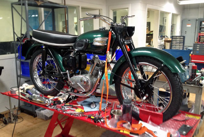
Final Rebuild

