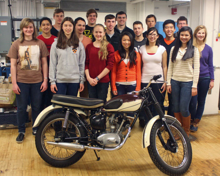
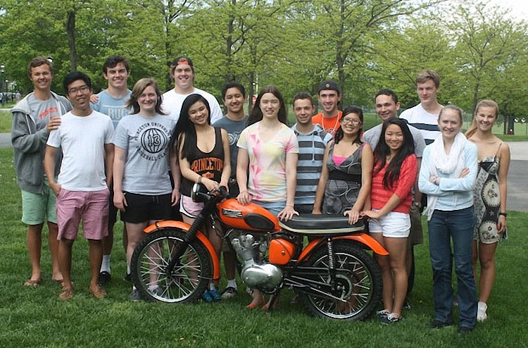
The Class of 2012 - 2013
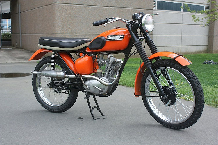
Project - 1959 Tiger Cub
Project - 1959 Tiger Cub
List of Problems ….
- Cylinder bore .025-over using .020-over piston – ring gap too large
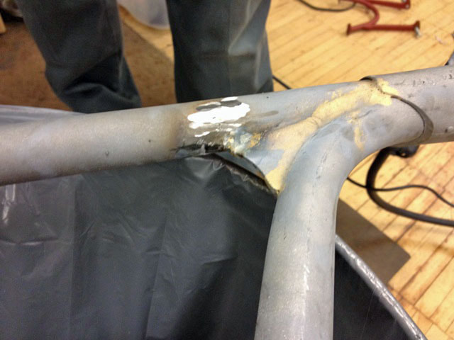
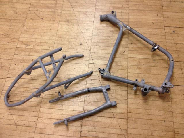
- Frame rusted and cracked; engine mount cracked
- Valves beyond restoration by grinding
- Valve guides loose
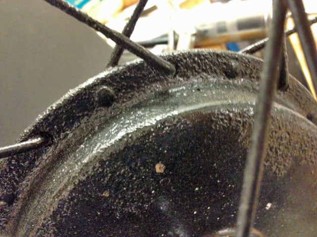
- Spokes and wheel hubs rusted
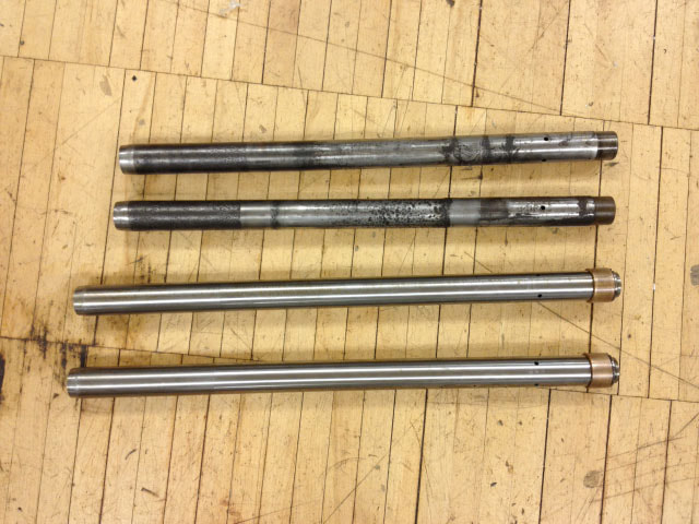
- Fork tubes (stanchions) heavily pitted
- Transmission cogs on one set of gears damaged
- Bronze bushing worn on one of the transmission gears
- Clutch plates heavily rusted
- Distributor missing parts including advance mechanism
- Wrong handlebar
- Portion of head ground away so that copper gasket (between head and barrel) would not seal
- Internal bolt fused to engine case
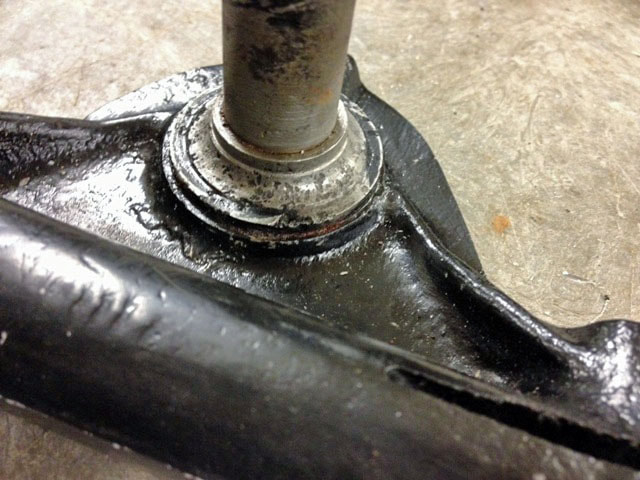
- Ball race in steering column pitted
- Flywheel bushing worn
|
Bottom End
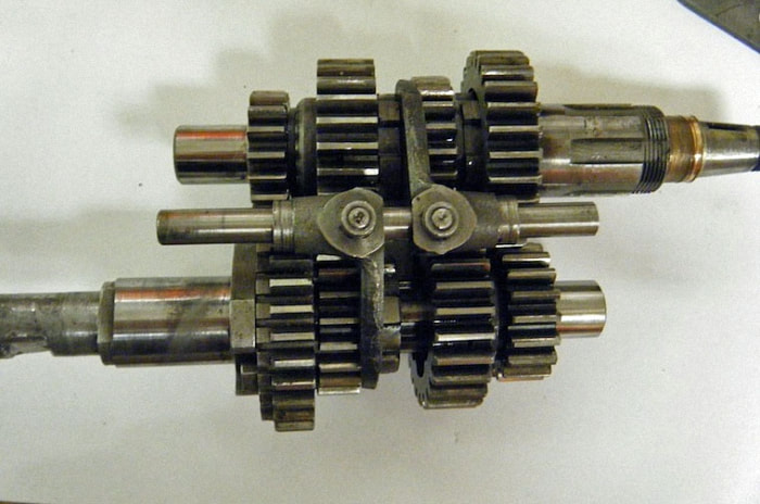
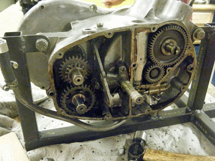
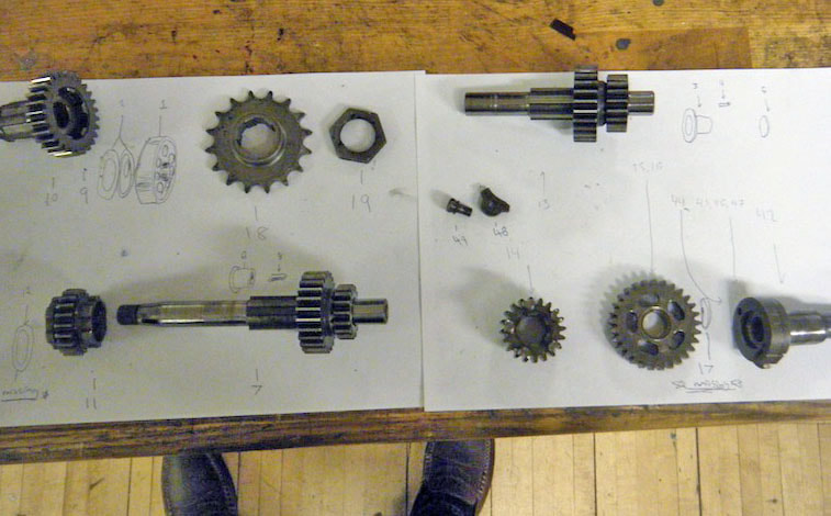
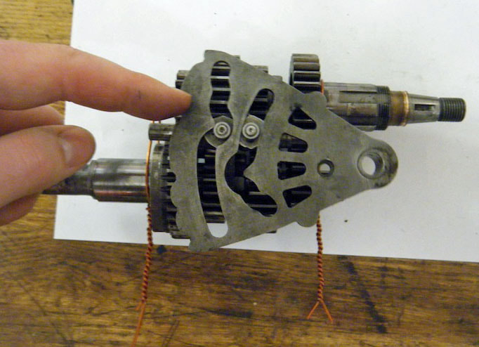
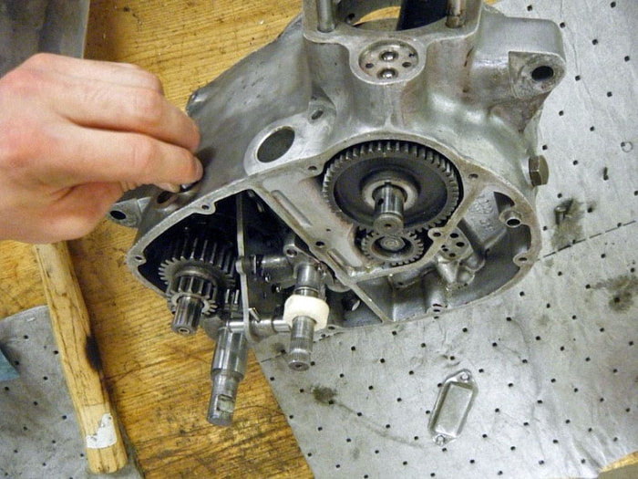
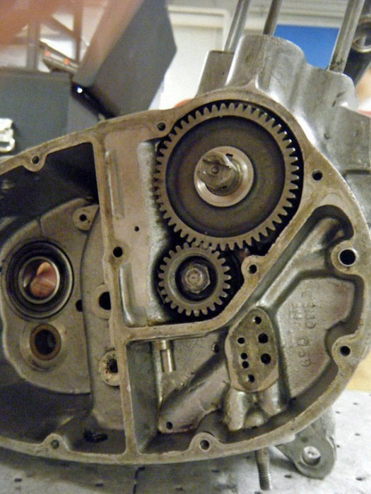
Here is our engine without the engine covers and before we removed any internal components. Shown is the transmission (left), the cam (right), the gear change spindle and shifter plate (middle), and the oil pump (starting under the cam, wrapping underneath to the left). This is the exploded view of our transmission (the parts which remain inside the engine casing are drawn in). The transmission converts power from the flywheel rotation into power that turns the drive sprocket. The ratios for this specific motorcycle transmission are 2.72:1 for 1st gear, 1.56:1 for 2nd, 1.20:1 for 3rd, and 1.00:1.00 for 4th. Those ratios mean that every 2.72 turns of the input shaft yield 1 full turn of the output shaft when the bike is in first gear, 1.56 turns yield 1 turn when in second, and so on. This is the transmission assembled as it would be inside the engine in first gear. The selector fork has pushed the bottom gear to the left, engaging it with another gear, and putting the assembly in first gear. |
The transmission as it is assembled here is as it would be inside the engine in third gear. The selector fork has pushed the top gear to the left, engaging it with the another gear, and putting the assembly in third gear.
Also shown is the shifter plate, which has channels to guide the rollers on the selector forks to the proper position. The notches on the end of the plate are called detents, and a spring inside the engine slips into those detents to lock the plate in place so that it will not accidentally slip out.
Also shown is the shifter plate, which has channels to guide the rollers on the selector forks to the proper position. The notches on the end of the plate are called detents, and a spring inside the engine slips into those detents to lock the plate in place so that it will not accidentally slip out.
|
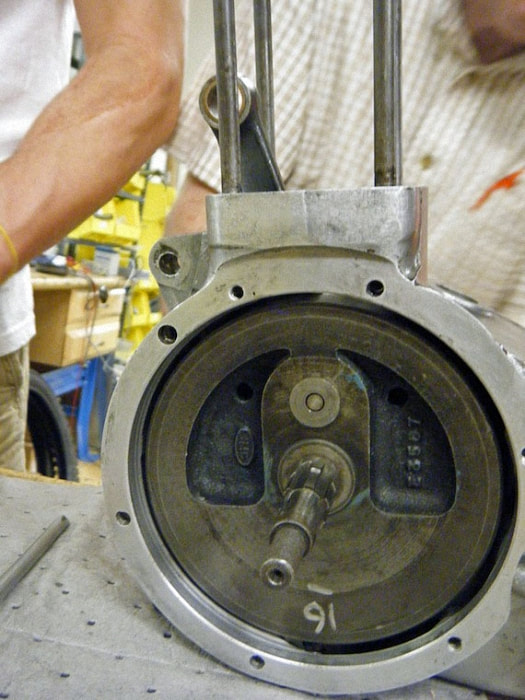
Here is the flywheel inside the engine casing. When the explosion in the barrel drives the piston downward, it pushes a rod which connects to the flywheel, downward too.
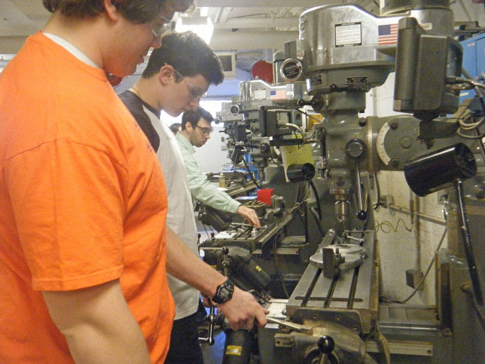
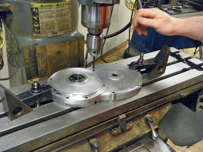
The flywheel is very heavy so that it has enough momentum to use the energy from that one explosion to drive the piston three more strokes before the next explosion. The rotation of the flywheel transfers power to the input shaft of the transmission. Finding gasket coordinates, we used the milling machine’s XY plane to find the coordinates for all the screw holes in the engine cover. We then put those coordinates into the CAD program to create the shape the laser would use to cut out the gasket. The picture shows the cam inside the engine. The cam has lobes push tappets that in turn drive push-rods attached to valves. The valves control when oxygen enters the barrel, so the cam timing is crucial to an effective explosion in the engine. |
Clutch
Team - Andrew, Dan, and Danny
Pics show:
Clutch in pieces
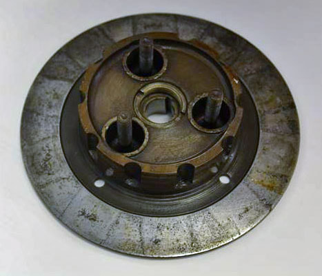
Back Plate – connected to main shaft and transfer rotational energy from clutch basket to transmission.
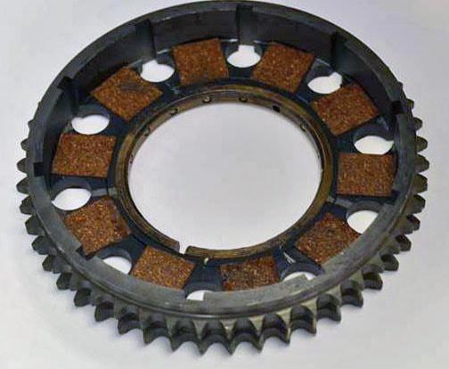
Clutch Basket – houses the clutch plates and is connected to primary chain. Specs: 48 teeth (vs. 18 on engine sprocket) Ratio: 2.67 / 1
Plates : Friction plate - connected to clutch basket. Driven plate - connected to inner hub. When clutch depressed - both spin freely. When clutch not depressed, surface friction prevents slippage (allows transfer of energy).
Specs:
Thickness: 1/8 in
Diameter: 4.95 in
Specs:
Thickness: 1/8 in
Diameter: 4.95 in
|
Cups and Springs
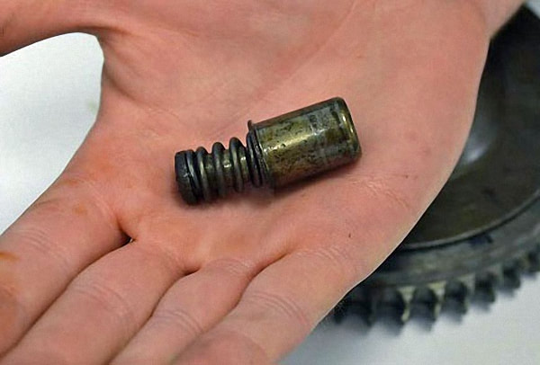
Purpose: Compress the clutch plates together when clutch is not engaged. Specs: Free length: 1.4 in : Compressed length (for testing): .77 in Force applied during testing: 40lbs=177.93N Spring constant: 761lbs/ft = 11,120.55 N/m |
Lever
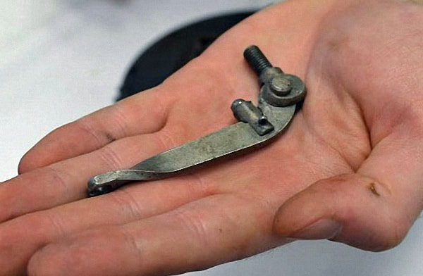
Purpose: Utilize mechanical advantage to lower the force needed on the handle. Specs: Distance from pivot to push rod: .25 in Distance from push rod to applied force from cable: 2.5 in Mechanical advantage: 5:1 |
Cylinder Barrel
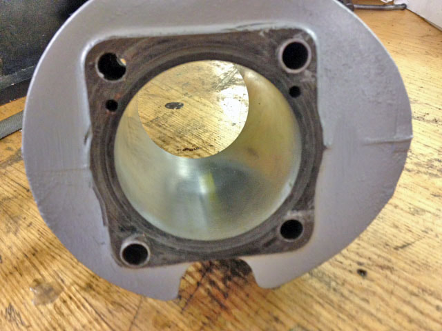
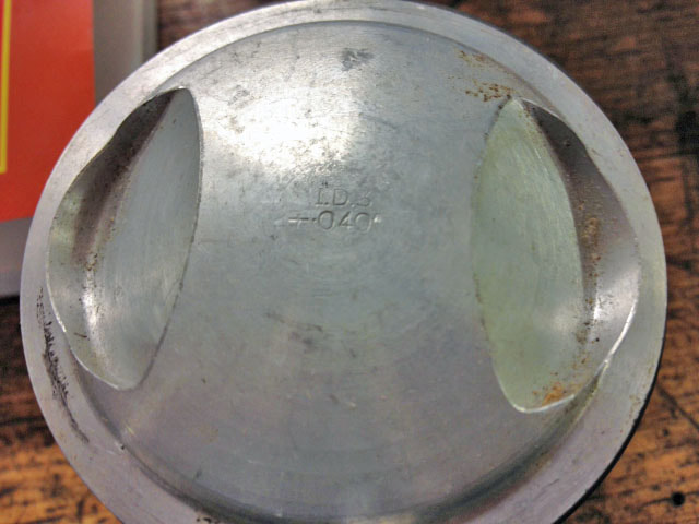
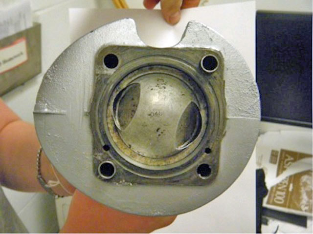
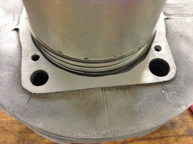
Our cylinder was originally 20 over (0.020”). The piston and piston rings had a big gap however so we decided we needed to go up a piston size to 0.030”.
The gap needs to be small in order to seal the chamber and keep oil from leaking past. Also, if there are sharp edges (such as the end of the rings if the gap is too big), heat will concentrate in these areas.
|
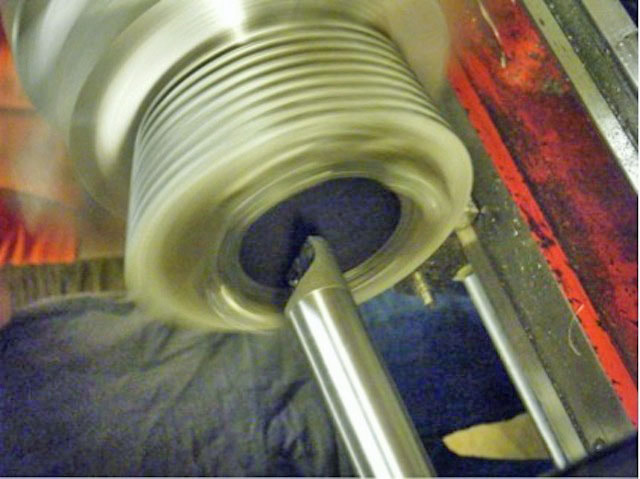
In order for the 0.030" piston to fit, we began boring out the cylinder. As we proceeded however we noticed a small axial crack that ran the entire length so we had to continue boring out small layers of material until finally the crack was gone. We then used a telescoping device to measure the new bore of the cylinder, only to realize it was slightly bigger than 0.030”.
We did not want to bore the cylinder too far and risk compromising the walls, but we still had a fair amount of room to work with and we continued boring until the cylinder was at 0.040”. We then ordered a 40 over piston, domed for a 9:1 compression ratio. |
|
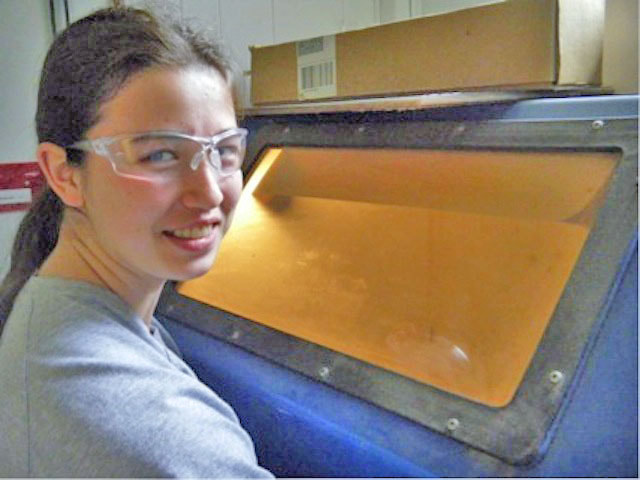
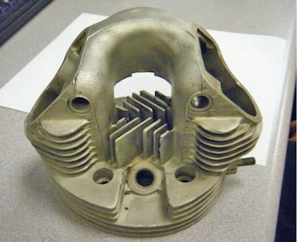
To clean the barrel and head, a sandblaster was used to remove built up carbon and remove paint. The sandblaster is a sealed container with a window and two thick gloves. This allows you to safely move the object within the sandblaster. Underneath the grill is a funnel where the sand collects and it is this that the suction tube picks up to re-use. We then spray painted the barrel silver. To do this, all the openings which the paint could have gotten into were taped over and a bit of oil was rubbed into the cylinder. The oil would prevent any paint that did get in from sticking to the metal. Then, by hanging it up on a wire, we sprayed the paint on from all directions to make an even coating. |
Afterwards, we hung it up to dry. The spray paint used was specifically designed to withstand the high temperatures of a combustion engine.
Cylinder Head
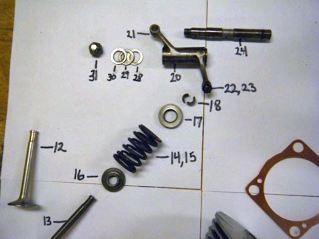
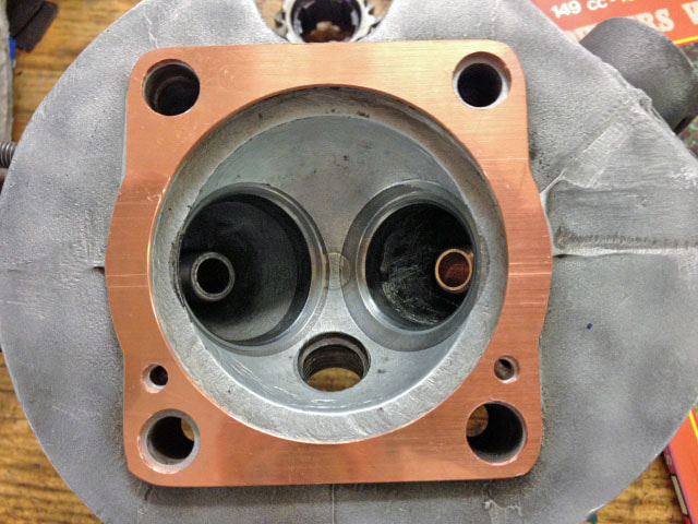
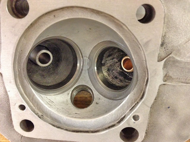
The valve guides were found to be worn and it is very important to get two things right when servicing the valves; the alignment of the valve guides has to be perfect and the valve seats has to fit onto the valves perfectly so as to seal correctly.
Glenn assisted us with aligning the valve guides, since this had to be incredibly accurate and was awkwardly located on the inside of the cylinder head.
|
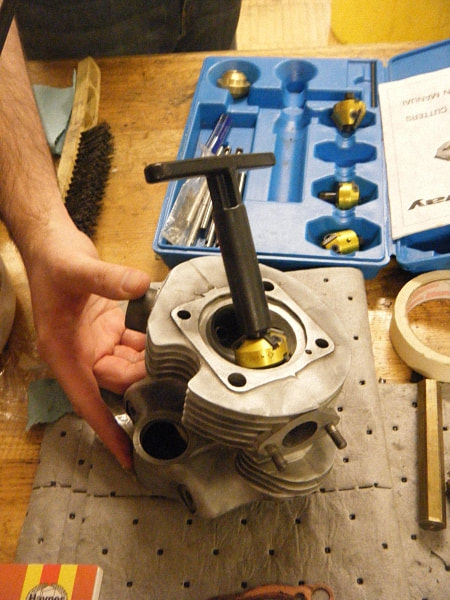
We were however able to prepare the valve seats. This involved cutting the valve seats with a specialized tool that resembled a spinning top mounted on a rod which ran through the valve guide.
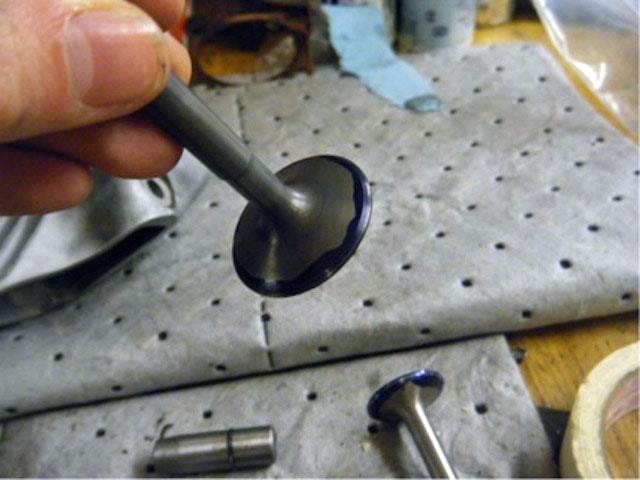
The “spinning top” had blades mounted on its sides at specific angles. First the valve was cut with the 46° blades and then the 60° blades. The work was tedious as the blades had to be rotated until no ridges could be felt. Once this was done the quality of the join was tested by “bluing” the valves. A heavily pigmented, alcohol based, blue solution was applied to the circumference of the valves and the valves were spun in place. A good “bluing” result is a narrow ring on or almost on the join between the 46° and 60° cuts. The cutting was repeated until the bluing result was good. Next, an abrasive paste was applied to the surface of the valves and the valves were rotated in place. This was to ensure that the meet was complete all the way around the seat and that any inconsistencies were ironed out. Removing all of the abrasive after this step is incredibly important as any remnant abrasive could make its way into the combustion chamber and down the cylinder, potentially causing damage to the cylinder. |
|
Frame, Wheels and Suspension
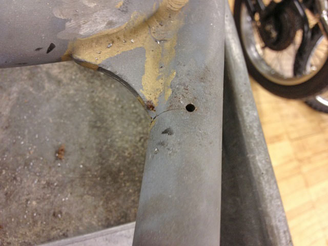
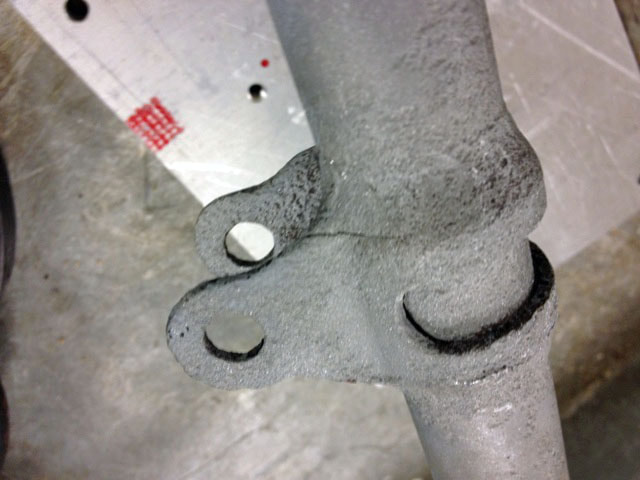
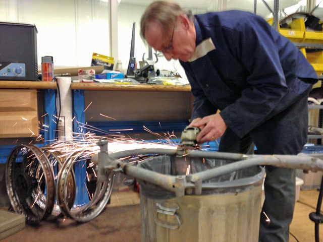
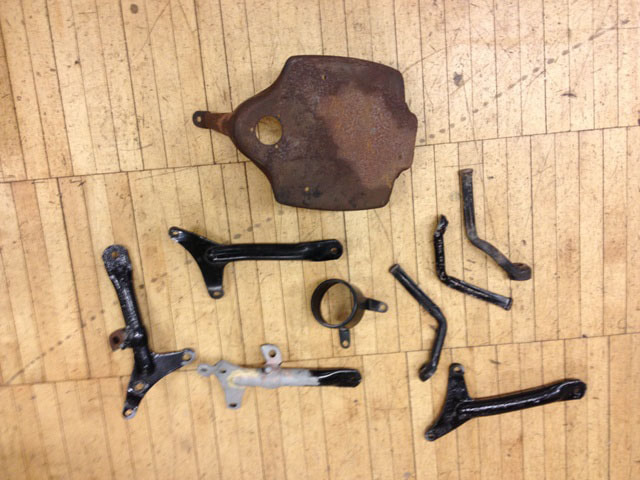
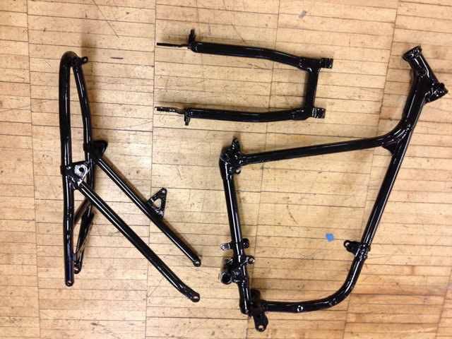
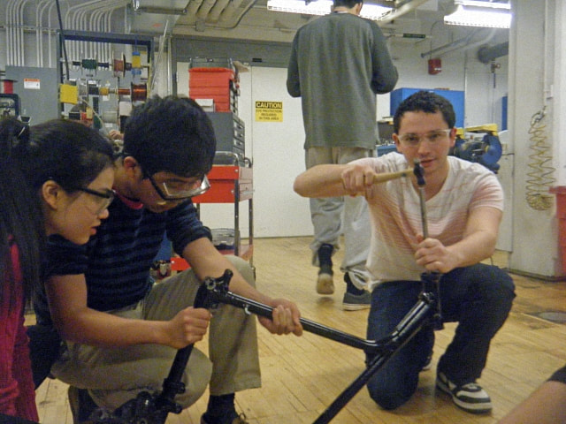
A major crack was discovered after sand-blasting the frame. The first general solution to this problem is to cut out a section of the frame and weld a new section in, in it’s place (however it can be difficult to align the insert correctly). Instead Glenn opted for the second general solution: Pilot holes were drilled at either end of the crack, a V-groove was drilled along the crack and steel was welded into the groove. We learned about Magna-flux testing, a method used to find concealed cracks in frames. We also found another crack on the frame around an engine mounting, the wheel spokes and hubs rusted, the fork tubes (stanchions) heavily pitted, wrong handlebars fitted and the lower ball race in steering column pitted. |
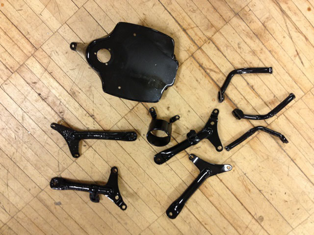
Painting and the final Rebuild

